
Installation Manual

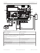
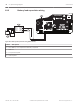
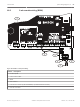
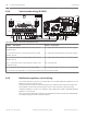

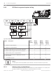

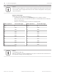
Table Of Contents
- Title Page
- Table of Contents
- Certifications, approvals, listings, and safety
- Introduction
- System overview
- Installation checklist
- Control panel installation
- Power supply
- Telephone communications
- IP communications
- Keypads, keyswitches, keyfobs and transmitters
- Keypads
- B915 Basic Keypad
- B920 Two-line Alphanumeric Keypad
- B921C Two-line Capacitive Keypad with Inputs
- B930 ATM Style Alphanumeric Keypad
- B942 Touch Screen Keypad
- Shortcuts and custom functions
- Address settings
- Supervision
- Installation and control panel wiring (keypads)
- Sensor loops overview and wiring (B921C/B942/B942W only)
- Output wiring (B942/B942W only)
- Troubleshooting
- Keyswitches
- RADION keyfobs and Inovonics pendant transmitters
- Keypads
- On-board outputs
- Off-board outputs
- On-board points
- Off-board points
- Wireless modules
- Access control
- Program and test the control panel
- Control panel board overview
- System wiring diagrams
- Approved applications
- Keypad Installer menu
- [1] Program menu
- [1] Reporting > [1] Phone menu parameters
- [1] Reporting > [2] Network menu parameters
- [1] Reporting > [3] Routing menu parameters
- [1] Reporting > [4] Personal Note menu parameters
- [2] Network > [1] Ethernet > (choose the bus module or on-board) > [1] Module Parameters menu
- [2] Network > [1] Ethernet > (choose the bus module or on-board) > [2] Address Parameters menu
- [2] Network > [1] Ethernet > (choose the bus module or on-board) > [3] DNS Parameters menu
- [2] Network > [2] Cellular > (choose the SDI2 cellular module or plug-in module)
- [3] RPS > [1] RPS Passcode menu parameters
- [3] RPS > [2] RPS Phone Number menu parameters
- [3] RPS > [3] RPS IP Address menu parameters
- [3] RPS > [4] RPS Port Number menu parameters
- [4] Area Options menu parameters
- [5] Keypad menu parameters
- [6] Users menu parameters
- [7] Points menu parameters
- [8] Disable Programming menu
- [2] Wireless menu
- [1] RF Point Menu> [1] Enroll Point RFID
- [1] RF Point Menu> [2] Replace Point RFID
- [1] RF Point Menu> [3] Remove Point RFID
- [2] RF Repeater Menu > [1] Add Repeater
- [2] RF Repeater Menu > [2] Replace Repeater
- [2] RF Repeater Menu > [3] Remove Repeater
- [3] RF Diagnostic Menu > [1] RF Points
- [3] RF Diagnostic Menu > [2] RF Repeater Menu
- [3] Diags menu
- [4] Serv Byp (Service Bypass) menu
- [5] Versions menu
- [6] Cloud menu
- [1] Program menu
- Specifications
- Appendix
- Back Page

SDI2 devices general system wiring
1 21
7
6
4
2
5
3
7 COM 8
C
OUTPUT
B
1 k End of Line Resistors
Voltage Ranges
ON-BOARD POINTS
3.7 - 5.0 VDC
2.0 - 3.0 VDC
0.0 - 1.3 VDC
Open
Normal
Short
3 COM 4 5 COM 61 COM 2
R Y G B
SDI2
Device Bus
AUX
- 12 V +
TMPR
1 COM 2 7 COM 83 COM 4 5 COM 6
RESET
COM AUX
R Y G B
PWR A B COM
B C
OUTPUT
Figure 18.6: SDI2 devices system wiring (B5512 shown)
Callout ᅳ Description B6512
capacity
B5512/
B5512E
capacity
B4512/
B4512E
capacity
B3512/
B3512E
capacity
1 ᅳ B208 Octo-input Modules 9 4 2 0
2 ᅳ B308 Octo-output Modules 9 5 3 0
3 ᅳ B426 Conettix Ethernet Communication Modules 1 1 1 1
4 ᅳ B450 Conettix Plug-in Communicator Interfaces 1 1 1 1
5 ᅳ B520 Auxiliary Power Supply Modules 4 4 2 2
6 ᅳ B810 wireless receivers or B820 SDI2 Inovonics
Interface Modules
1 1 1 1
7 ᅳ Compatible keypads 12 8 8 4
Notice!
The SDI2 power terminal (R/PWR) is power limited. The SDI2 terminals are supervised.
SDI2 bus wiring recommendations
Use the following SDI2 bus wiring recommendations for SDI2 installation. The control panel
and SDI2 modules use the SDI2 bus to communicate with one another.
18.6
18.6.1
88 en | System wiring diagrams Control Panel
2016.05 | 14 | F.01U.287.180 Installation and System Reference Guide Bosch Security Systems, Inc.