
Installation Manual
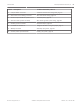

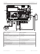
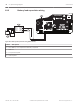
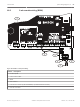

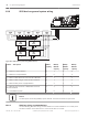

Table Of Contents
- Title Page
- Table of Contents
- Certifications, approvals, listings, and safety
- Introduction
- System overview
- Installation checklist
- Control panel installation
- Power supply
- Telephone communications
- IP communications
- Keypads, keyswitches, keyfobs and transmitters
- Keypads
- B915 Basic Keypad
- B920 Two-line Alphanumeric Keypad
- B921C Two-line Capacitive Keypad with Inputs
- B930 ATM Style Alphanumeric Keypad
- B942 Touch Screen Keypad
- Shortcuts and custom functions
- Address settings
- Supervision
- Installation and control panel wiring (keypads)
- Sensor loops overview and wiring (B921C/B942/B942W only)
- Output wiring (B942/B942W only)
- Troubleshooting
- Keyswitches
- RADION keyfobs and Inovonics pendant transmitters
- Keypads
- On-board outputs
- Off-board outputs
- On-board points
- Off-board points
- Wireless modules
- Access control
- Program and test the control panel
- Control panel board overview
- System wiring diagrams
- Approved applications
- Keypad Installer menu
- [1] Program menu
- [1] Reporting > [1] Phone menu parameters
- [1] Reporting > [2] Network menu parameters
- [1] Reporting > [3] Routing menu parameters
- [1] Reporting > [4] Personal Note menu parameters
- [2] Network > [1] Ethernet > (choose the bus module or on-board) > [1] Module Parameters menu
- [2] Network > [1] Ethernet > (choose the bus module or on-board) > [2] Address Parameters menu
- [2] Network > [1] Ethernet > (choose the bus module or on-board) > [3] DNS Parameters menu
- [2] Network > [2] Cellular > (choose the SDI2 cellular module or plug-in module)
- [3] RPS > [1] RPS Passcode menu parameters
- [3] RPS > [2] RPS Phone Number menu parameters
- [3] RPS > [3] RPS IP Address menu parameters
- [3] RPS > [4] RPS Port Number menu parameters
- [4] Area Options menu parameters
- [5] Keypad menu parameters
- [6] Users menu parameters
- [7] Points menu parameters
- [8] Disable Programming menu
- [2] Wireless menu
- [1] RF Point Menu> [1] Enroll Point RFID
- [1] RF Point Menu> [2] Replace Point RFID
- [1] RF Point Menu> [3] Remove Point RFID
- [2] RF Repeater Menu > [1] Add Repeater
- [2] RF Repeater Menu > [2] Replace Repeater
- [2] RF Repeater Menu > [3] Remove Repeater
- [3] RF Diagnostic Menu > [1] RF Points
- [3] RF Diagnostic Menu > [2] RF Repeater Menu
- [3] Diags menu
- [4] Serv Byp (Service Bypass) menu
- [5] Versions menu
- [6] Cloud menu
- [1] Program menu
- Specifications
- Appendix
- Back Page

Notice!
There can only be a difference of 2 volts (maximum) between the AUX power terminals of the
control panel or power supply and the device for the modules and keypads to work properly
under all conditions.
Maximum cable lengths
Follow these rules when wiring the SDI2 bus:
– The SDI2 bus requires the use of unshielded cable from 12 AWG to 22 AWG.
– Refer to the SDI2 device or keypad documentation for the allowable maximum distance
from the control panel.
– Maximum overall cable lengths are listed in the following table:
Cable capacitance Overall cable length Cable capacitance Overall cable length
pF/ft ft pF/ft ft
< 17 7500 27 5185
18 7500 28 5000
19 7350 29 4828
20 7000 30 4700
21 6666 31 4516
22 6363 32 4400
23 6086 33 4242
24 5800 34 4100
25 5600 35 4000
26 5385 36 3800
Table 18.1: Maximum cable length
Notice!
Use unshielded cable only.
Maximum capacitance of 140nF (140,000 pF) per system. Contact the wire manufacturer for
the capacitance ratings of the wire being used.
90 en | System wiring diagrams Control Panel
2016.05 | 14 | F.01U.287.180 Installation and System Reference Guide Bosch Security Systems, Inc.