
Installation Manual
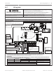
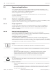


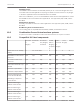
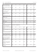


Table Of Contents
- Title Page
- Table of Contents
- Certifications, approvals, listings, and safety
- Introduction
- System overview
- Installation checklist
- Control panel installation
- Power supply
- Telephone communications
- IP communications
- Keypads, keyswitches, keyfobs and transmitters
- Keypads
- B915 Basic Keypad
- B920 Two-line Alphanumeric Keypad
- B921C Two-line Capacitive Keypad with Inputs
- B930 ATM Style Alphanumeric Keypad
- B942 Touch Screen Keypad
- Shortcuts and custom functions
- Address settings
- Supervision
- Installation and control panel wiring (keypads)
- Sensor loops overview and wiring (B921C/B942/B942W only)
- Output wiring (B942/B942W only)
- Troubleshooting
- Keyswitches
- RADION keyfobs and Inovonics pendant transmitters
- Keypads
- On-board outputs
- Off-board outputs
- On-board points
- Off-board points
- Wireless modules
- Access control
- Program and test the control panel
- Control panel board overview
- System wiring diagrams
- Approved applications
- Keypad Installer menu
- [1] Program menu
- [1] Reporting > [1] Phone menu parameters
- [1] Reporting > [2] Network menu parameters
- [1] Reporting > [3] Routing menu parameters
- [1] Reporting > [4] Personal Note menu parameters
- [2] Network > [1] Ethernet > (choose the bus module or on-board) > [1] Module Parameters menu
- [2] Network > [1] Ethernet > (choose the bus module or on-board) > [2] Address Parameters menu
- [2] Network > [1] Ethernet > (choose the bus module or on-board) > [3] DNS Parameters menu
- [2] Network > [2] Cellular > (choose the SDI2 cellular module or plug-in module)
- [3] RPS > [1] RPS Passcode menu parameters
- [3] RPS > [2] RPS Phone Number menu parameters
- [3] RPS > [3] RPS IP Address menu parameters
- [3] RPS > [4] RPS Port Number menu parameters
- [4] Area Options menu parameters
- [5] Keypad menu parameters
- [6] Users menu parameters
- [7] Points menu parameters
- [8] Disable Programming menu
- [2] Wireless menu
- [1] RF Point Menu> [1] Enroll Point RFID
- [1] RF Point Menu> [2] Replace Point RFID
- [1] RF Point Menu> [3] Remove Point RFID
- [2] RF Repeater Menu > [1] Add Repeater
- [2] RF Repeater Menu > [2] Replace Repeater
- [2] RF Repeater Menu > [3] Remove Repeater
- [3] RF Diagnostic Menu > [1] RF Points
- [3] RF Diagnostic Menu > [2] RF Repeater Menu
- [3] Diags menu
- [4] Serv Byp (Service Bypass) menu
- [5] Versions menu
- [6] Cloud menu
- [1] Program menu
- Specifications
- Appendix
- Back Page

Approved applications
The UL System Chart references the components that are evaluated and listed by UL for
compatibility with B6512/B5512/B4512/B3512 control panels. These components meet the
basic system requirements for the applicable standard.
Refer to Compatible UL listed components, page 97.
The system wiring diagrams show the relationship between the control panel and the
accessory components.
Refer to System wiring diagrams, page 82.
Optional compatible equipment
You can use UL Listed components not requiring evaluation for electrical compatibility in many
applications when installed according to the manufacturer’s instructions.
Burglar applications
You can use UL Listed components not requiring evaluation for electrical compatibility in
burglary applications. In some cases, you must use a UL Listed interface module with the
sensors. Consult the individual component specification and installation documents to
determine suitability.
Bank safe and vault applications
You must use the D8108A Attack-Resistant Enclosure to meet UL Standard 681.
Refer to Wiring information for installations using the Rothenbuhler 5110/4001-42 High Security
Bell, page 93 for wiring instructions and diagrams.
Control panel enclosure requirements
UL Standard 681 for Installation and Classification of Mercantile and Bank Burglary Alarm
Systems requires foil lining or equivalent protection of the control unit enclosure. The D8108A
Attack-Resistant Enclosure does not have a foil lining, but acceptable protection is provided by
mounting electronic vibration sensors inside the enclosure.
Notice!
Do not use proximity alarms (capacitance) to protect the control panel enclosure.
– Install the same electronic vibration sensors in the D8108A that are used to protect the
safe or vault.
– Mount the Sentrol 5402, Potter EVD-S, or Arrowhead S-3810 electronic vibration
detection (EVD) system inside the D8108A to meet the UL 681 requirements.
– Install and test the EVD sensor according to the manufacturer’s instructions.
– Mount the EVD sensor directly inside the metal cabinet of the D8108A.
!
Caution!
Do not install the EVD sensor within 6.4 mm (0.25 in) of the components or traces of the
printed circuit assembly.
Battery connections
– Using a D122 Dual Battery Harness, connect two 12 V 7 Ah batteries in the control panel
enclosure.
– Use a separate D8108A for the two 12 V 7 Ah batteries. When using a D122L Dual Battery
Harness, wire the batteries in parallel and connect the harness to the BAT+ and BAT-
terminals of the control panel.
19
19.1
19.1.1
19.1.2
92 en | Approved applications Control Panel
2016.05 | 14 | F.01U.287.180 Installation and System Reference Guide Bosch Security Systems, Inc.