
Installation Manual
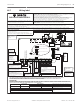
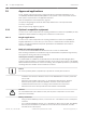


Table Of Contents
- Title Page
- Table of Contents
- Certifications, approvals, listings, and safety
- Introduction
- System overview
- Installation checklist
- Control panel installation
- Power supply
- Telephone communications
- IP communications
- Keypads, keyswitches, keyfobs and transmitters
- Keypads
- B915 Basic Keypad
- B920 Two-line Alphanumeric Keypad
- B921C Two-line Capacitive Keypad with Inputs
- B930 ATM Style Alphanumeric Keypad
- B942 Touch Screen Keypad
- Shortcuts and custom functions
- Address settings
- Supervision
- Installation and control panel wiring (keypads)
- Sensor loops overview and wiring (B921C/B942/B942W only)
- Output wiring (B942/B942W only)
- Troubleshooting
- Keyswitches
- RADION keyfobs and Inovonics pendant transmitters
- Keypads
- On-board outputs
- Off-board outputs
- On-board points
- Off-board points
- Wireless modules
- Access control
- Program and test the control panel
- Control panel board overview
- System wiring diagrams
- Approved applications
- Keypad Installer menu
- [1] Program menu
- [1] Reporting > [1] Phone menu parameters
- [1] Reporting > [2] Network menu parameters
- [1] Reporting > [3] Routing menu parameters
- [1] Reporting > [4] Personal Note menu parameters
- [2] Network > [1] Ethernet > (choose the bus module or on-board) > [1] Module Parameters menu
- [2] Network > [1] Ethernet > (choose the bus module or on-board) > [2] Address Parameters menu
- [2] Network > [1] Ethernet > (choose the bus module or on-board) > [3] DNS Parameters menu
- [2] Network > [2] Cellular > (choose the SDI2 cellular module or plug-in module)
- [3] RPS > [1] RPS Passcode menu parameters
- [3] RPS > [2] RPS Phone Number menu parameters
- [3] RPS > [3] RPS IP Address menu parameters
- [3] RPS > [4] RPS Port Number menu parameters
- [4] Area Options menu parameters
- [5] Keypad menu parameters
- [6] Users menu parameters
- [7] Points menu parameters
- [8] Disable Programming menu
- [2] Wireless menu
- [1] RF Point Menu> [1] Enroll Point RFID
- [1] RF Point Menu> [2] Replace Point RFID
- [1] RF Point Menu> [3] Remove Point RFID
- [2] RF Repeater Menu > [1] Add Repeater
- [2] RF Repeater Menu > [2] Replace Repeater
- [2] RF Repeater Menu > [3] Remove Repeater
- [3] RF Diagnostic Menu > [1] RF Points
- [3] RF Diagnostic Menu > [2] RF Repeater Menu
- [3] Diags menu
- [4] Serv Byp (Service Bypass) menu
- [5] Versions menu
- [6] Cloud menu
- [1] Program menu
- Specifications
- Appendix
- Back Page

R E D O R G W H T B L K
N/O 1
COMM 1
N/C
X1 -
X1+
2
1
4
3
2
1
1 632
COM AUX
P1
3
9
7
6
4
10
11
14
12
9
13
9
8
5
TMPR
1 COM 2 7 COM 83 COM 4 5 COM 6
RESET
ETHERNET
COM AUX
R Y G B
PWR A B COM
+ BAT -
18VAC
B C
OUTPUT
NO C NC
OUTPUT A
7 COM 8
C
OUTPUT
B
USB
ETHERNET
100BASE-T
LINK
COMMUNICATION MODULE 1
1 k End of Line Resistors
Voltage Ranges
ON-BOARD POINTS
3.7 - 5.0 VDC
2.0 - 3.0 VDC
0.0 - 1.3 VDC
Open
Normal
Short
3 COM 4 5 COM 61 COM 2
R Y G B
SDI2
Device Bus
18 VAC
OUTPUT A
AUX
- 12 V +
Figure 19.2: Detailed Rothenbuhler 5110_4001-42 High Security Bell to control panel wiring (B5512 shown)
1 ᅳ 5110 Logic Board
8 ᅳ Alarm input point*
2 ᅳ 4001-42 External Line Balancing Module 9 ᅳ 10 kΩ resistor
3 ᅳ Control panel set to OUTPUT A using AUX
PWR
10 ᅳ Optional silence switch
4 ᅳ Alarm output 11 ᅳ D133 Relay Module
5 ᅳ Alternate alarm (use B or C) 12 ᅳ BBL In 4
6 ᅳ Common 13 ᅳ BBL Out 5
7 ᅳ +12.0 VDC 14 ᅳ Terminal TB1
*
Use Terminals 1 through 8. (Select only one.)
Notice!
Bell Test at Arming: UL Standard 365 requires a Bell Test at arming for bank safe and vault
applications.
System configuration requirements
The following configuration and programming options are required for UL Bank Safe and Vault
Systems. Refer to RPS Help or the control panel's Program Entry Guide for programming
information.
94 en | Approved applications Control Panel
2016.05 | 14 | F.01U.287.180 Installation and System Reference Guide Bosch Security Systems, Inc.