
Installation Manual
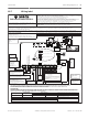
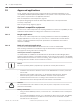


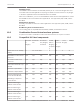
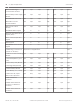


Table Of Contents
- Title Page
- Table of Contents
- Certifications, approvals, listings, and safety
- Introduction
- System overview
- Installation checklist
- Control panel installation
- Power supply
- Telephone communications
- IP communications
- Keypads, keyswitches, keyfobs and transmitters
- Keypads
- B915 Basic Keypad
- B920 Two-line Alphanumeric Keypad
- B921C Two-line Capacitive Keypad with Inputs
- B930 ATM Style Alphanumeric Keypad
- B942 Touch Screen Keypad
- Shortcuts and custom functions
- Address settings
- Supervision
- Installation and control panel wiring (keypads)
- Sensor loops overview and wiring (B921C/B942/B942W only)
- Output wiring (B942/B942W only)
- Troubleshooting
- Keyswitches
- RADION keyfobs and Inovonics pendant transmitters
- Keypads
- On-board outputs
- Off-board outputs
- On-board points
- Off-board points
- Wireless modules
- Access control
- Program and test the control panel
- Control panel board overview
- System wiring diagrams
- Approved applications
- Keypad Installer menu
- [1] Program menu
- [1] Reporting > [1] Phone menu parameters
- [1] Reporting > [2] Network menu parameters
- [1] Reporting > [3] Routing menu parameters
- [1] Reporting > [4] Personal Note menu parameters
- [2] Network > [1] Ethernet > (choose the bus module or on-board) > [1] Module Parameters menu
- [2] Network > [1] Ethernet > (choose the bus module or on-board) > [2] Address Parameters menu
- [2] Network > [1] Ethernet > (choose the bus module or on-board) > [3] DNS Parameters menu
- [2] Network > [2] Cellular > (choose the SDI2 cellular module or plug-in module)
- [3] RPS > [1] RPS Passcode menu parameters
- [3] RPS > [2] RPS Phone Number menu parameters
- [3] RPS > [3] RPS IP Address menu parameters
- [3] RPS > [4] RPS Port Number menu parameters
- [4] Area Options menu parameters
- [5] Keypad menu parameters
- [6] Users menu parameters
- [7] Points menu parameters
- [8] Disable Programming menu
- [2] Wireless menu
- [1] RF Point Menu> [1] Enroll Point RFID
- [1] RF Point Menu> [2] Replace Point RFID
- [1] RF Point Menu> [3] Remove Point RFID
- [2] RF Repeater Menu > [1] Add Repeater
- [2] RF Repeater Menu > [2] Replace Repeater
- [2] RF Repeater Menu > [3] Remove Repeater
- [3] RF Diagnostic Menu > [1] RF Points
- [3] RF Diagnostic Menu > [2] RF Repeater Menu
- [3] Diags menu
- [4] Serv Byp (Service Bypass) menu
- [5] Versions menu
- [6] Cloud menu
- [1] Program menu
- Specifications
- Appendix
- Back Page

Safe and Vault protective circuits
To test the devices that protect the safe(s) or vault(s) without sounding the bell, specify the
devices’ points as controlled zones and supervised for trouble conditions. Refer to Point Index
in RPS Help or the control panel's Program Entry Guide more information.
Bell configuration
– UL 365 requires a bell time of 15 to 30 min. The Rothenbuhler 5110 Bell provides
selectable bell time through manipulation of its jumpers. Refer to the manufacturer’s
installation instructions for more information.
– In addition to the jumper settings inside the bell, you can activate the control panel for a
bell time of 15 min.
– UL 365 requires a Bell Test at arming and you must enable it in control panel
programming.
– Refer to the various bell parameters in RPS Help or the control panel's Program Entry
Guide for more bell time and test programming information.
Bell test
– To enable the bell test feature, you enable an unused area of the control panel. Enable
the bell test feature for the unused area only. Program OUTPUT B as the area bell output
for the unused area.
– Make all passcodes with authority to arm the safe or vault and also send a Closing Report
valid in this area. Program the area for a five-second exit delay.
– To complete the installation for this feature, connect the output to a D134 Dual Relay
Module.
Exit delay
Do not program the control panel’s maximum exit delay longer than 30 seconds.
Fire applications
You can use UL Listed fire initiating devices not requiring electrical compatibility evaluation in
any application. For example, the four-wire smoke detectors, heat detectors, waterflow
switches, and manual pull stations are suitable fire initiating devices. Consult the individual
component specification and installation documents to determine suitability.
Notice!
UL requires that the control panel supervises any device powered from a power output.
Notice!
The control panel does not support multiple detectors in alarm. The control panel is
compatible with detectors with optional features. Do not mix detectors from different
manufacturers on the same circuit.
Four-wire smoke detectors
When using four-wire smoke detectors, install a power supervision device according to the
manufacturer’s instructions. You can connect any number of four-wire smoke detectors to the
control panel (subject to available auxiliary power).
The Reset Sensor command is available from the keypads when the Reset Sensor is enabled.
Connect the smoke detectors to a suitable interface such as the B208 Octo-input Module or
on-board point to meet UL and NFPA requirements.
Notification Appliance Circuit (NAC)
Refer to Notification appliance circuit wiring, page 86.
19.1.3
Control Panel Approved applications | en 95
Bosch Security Systems, Inc. Installation and System Reference Guide 2016.05 | 14 | F.01U.287.180