
Installation Manual
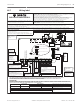


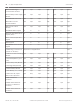


Table Of Contents
- Title Page
- Table of Contents
- Certifications, approvals, listings, and safety
- Introduction
- System overview
- Installation checklist
- Control panel installation
- Power supply
- Telephone communications
- IP communications
- Keypads, keyswitches, keyfobs and transmitters
- Keypads
- B915 Basic Keypad
- B920 Two-line Alphanumeric Keypad
- B921C Two-line Capacitive Keypad with Inputs
- B930 ATM Style Alphanumeric Keypad
- B942 Touch Screen Keypad
- Shortcuts and custom functions
- Address settings
- Supervision
- Installation and control panel wiring (keypads)
- Sensor loops overview and wiring (B921C/B942/B942W only)
- Output wiring (B942/B942W only)
- Troubleshooting
- Keyswitches
- RADION keyfobs and Inovonics pendant transmitters
- Keypads
- On-board outputs
- Off-board outputs
- On-board points
- Off-board points
- Wireless modules
- Access control
- Program and test the control panel
- Control panel board overview
- System wiring diagrams
- Approved applications
- Keypad Installer menu
- [1] Program menu
- [1] Reporting > [1] Phone menu parameters
- [1] Reporting > [2] Network menu parameters
- [1] Reporting > [3] Routing menu parameters
- [1] Reporting > [4] Personal Note menu parameters
- [2] Network > [1] Ethernet > (choose the bus module or on-board) > [1] Module Parameters menu
- [2] Network > [1] Ethernet > (choose the bus module or on-board) > [2] Address Parameters menu
- [2] Network > [1] Ethernet > (choose the bus module or on-board) > [3] DNS Parameters menu
- [2] Network > [2] Cellular > (choose the SDI2 cellular module or plug-in module)
- [3] RPS > [1] RPS Passcode menu parameters
- [3] RPS > [2] RPS Phone Number menu parameters
- [3] RPS > [3] RPS IP Address menu parameters
- [3] RPS > [4] RPS Port Number menu parameters
- [4] Area Options menu parameters
- [5] Keypad menu parameters
- [6] Users menu parameters
- [7] Points menu parameters
- [8] Disable Programming menu
- [2] Wireless menu
- [1] RF Point Menu> [1] Enroll Point RFID
- [1] RF Point Menu> [2] Replace Point RFID
- [1] RF Point Menu> [3] Remove Point RFID
- [2] RF Repeater Menu > [1] Add Repeater
- [2] RF Repeater Menu > [2] Replace Repeater
- [2] RF Repeater Menu > [3] Remove Repeater
- [3] RF Diagnostic Menu > [1] RF Points
- [3] RF Diagnostic Menu > [2] RF Repeater Menu
- [3] Diags menu
- [4] Serv Byp (Service Bypass) menu
- [5] Versions menu
- [6] Cloud menu
- [1] Program menu
- Specifications
- Appendix
- Back Page

Notice!
Test Weekly: Perform a Fire Test weekly.
Further information
– Standby battery calculations, page 99
– Household Fire Warning equipment, page 101
NFPA Style A (Class “B”) Circuit
Loops A and B on the D125B Module are NFPA Style A (Class “B”) initiating circuits suitable
for connecting any fire alarm initiating device, including two-wire and four-wire smoke
detectors.
Connecting initiating devices to on-board points (1 through 8) on the control panel:
– Use a D125B Powered Loop Interface Module with two-wire initiating devices.
– Use a D129 Dual Class “A” (NFPA Style D) Initiating Circuit Module with any type of
initiating device, except a two-wire smoke detector.
Connecting initiating devices to off-board points:
– Do not connect two-wire smoke detectors to POPITs or MUX bus inputs.
– Use the D9127U or D9127T POPIT Modules to connect four-wire smoke.
Other devices
Use a D130 Relay Module, D8129 OctoRelay, or Switched Aux (Terminal 8) to provide reset
capability to other initiating devices such as:
– B308 Octo-output Module
– D125B Powered Loop Interface Module (2-wire smoke detector module)
– D129 Dual “Class A” Initiation Circuit Module (4-wire smoke detector)
– D9127T/U POPITs
– On-board points
Install devices according to the manufacturer’s instructions. For more information, refer to Off-
board outputs, page 62.
For battery calculations, refer to Standby battery requirements and calculations, page 99.
Notice!
Test Weekly: Perform a Fire Test weekly. According to UL 864, a Fire Test tests both the AC
power and the battery.
Enclosures
Mount the control panel assembly in any of the Bosch Security Systems, Inc. enclosures listed:
– B10 Medium Control Panel Enclosure
– B11 Small Control Panel Enclosure
– D2203 Enclosure
– B8103 Universal Enclosure*/D8103 Universal Enclosure*
– D8109 Fire Enclosure (red)*
– D8108A Attack Resistant Enclosure*
*Requires a B12 mounting bracket.
B10, B11, D2203, and D8103 enclosures
The B10, B11, D2203, and D8103 enclosures are suitable for residential fire and burglary
installations and commercial burglary applications that do not require attack resistance or the
approval by Factory Mutual (FM) or New York City – Materials and Equipment Acceptance
(NYC-MEA). Refer to Compatible UL listed components, page 97 for acceptable applications.
19.1.4
96 en | Approved applications Control Panel
2016.05 | 14 | F.01U.287.180 Installation and System Reference Guide Bosch Security Systems, Inc.