
Installation Manual
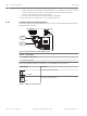
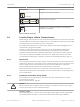
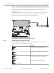
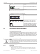
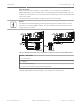
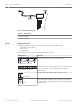
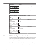
Table Of Contents
- Title Page
- Table of Contents
- Certifications, approvals, listings, and safety
- Introduction
- System overview
- Installation checklist
- Control panel installation
- Power supply
- Telephone communications
- IP communications
- Keypads, keyswitches, keyfobs and transmitters
- Keypads
- B915 Basic Keypad
- B920 Two-line Alphanumeric Keypad
- B921C Two-line Capacitive Keypad with Inputs
- B930 ATM Style Alphanumeric Keypad
- B942 Touch Screen Keypad
- Shortcuts and custom functions
- Address settings
- Supervision
- Installation and control panel wiring (keypads)
- Sensor loops overview and wiring (B921C/B942/B942W only)
- Output wiring (B942/B942W only)
- Troubleshooting
- Keyswitches
- RADION keyfobs and Inovonics pendant transmitters
- Keypads
- On-board outputs
- Off-board outputs
- On-board points
- Off-board points
- Wireless modules
- Access control
- Program and test the control panel
- Control panel board overview
- System wiring diagrams
- Approved applications
- Keypad Installer menu
- [1] Program menu
- [1] Reporting > [1] Phone menu parameters
- [1] Reporting > [2] Network menu parameters
- [1] Reporting > [3] Routing menu parameters
- [1] Reporting > [4] Personal Note menu parameters
- [2] Network > [1] Ethernet > (choose the bus module or on-board) > [1] Module Parameters menu
- [2] Network > [1] Ethernet > (choose the bus module or on-board) > [2] Address Parameters menu
- [2] Network > [1] Ethernet > (choose the bus module or on-board) > [3] DNS Parameters menu
- [2] Network > [2] Cellular > (choose the SDI2 cellular module or plug-in module)
- [3] RPS > [1] RPS Passcode menu parameters
- [3] RPS > [2] RPS Phone Number menu parameters
- [3] RPS > [3] RPS IP Address menu parameters
- [3] RPS > [4] RPS Port Number menu parameters
- [4] Area Options menu parameters
- [5] Keypad menu parameters
- [6] Users menu parameters
- [7] Points menu parameters
- [8] Disable Programming menu
- [2] Wireless menu
- [1] RF Point Menu> [1] Enroll Point RFID
- [1] RF Point Menu> [2] Replace Point RFID
- [1] RF Point Menu> [3] Remove Point RFID
- [2] RF Repeater Menu > [1] Add Repeater
- [2] RF Repeater Menu > [2] Replace Repeater
- [2] RF Repeater Menu > [3] Remove Repeater
- [3] RF Diagnostic Menu > [1] RF Points
- [3] RF Diagnostic Menu > [2] RF Repeater Menu
- [3] Diags menu
- [4] Serv Byp (Service Bypass) menu
- [5] Versions menu
- [6] Cloud menu
- [1] Program menu
- Specifications
- Appendix
- Back Page

– Communication supervision. The control panel supervises the communication path by
polling the central station receiver. If the poll is missed from either side, a communication
fault is declared both at the control panel and the central station receiver.
B426 module faults
With a B426 installed, several services become available to the control panel. Any break in the
Ethernet connection to a supervised B426 results in a system fault at the keypads indicating
Open Cable trouble.
If a Domain Name Server (DNS) is available on the network, a failure to resolve an individual
Network Address hostname results in a system fault at the keypads indicating DNS ERROR ##.
The error number represents the communication module and destination combination that
failed. Refer to RPS Help or the control panel's Program Entry Guide for details on
communication module/destination combinations. The keypad shows a failure to resolve the
domain name used for RPS Network Address.
If a B426 fails all communication with the DNS, a system fault indicating Network Module #
Address Error shows on all keypads and the control panel sends a trouble event to the central
stations, if enabled.
Local RPS programming
Use the B426 IP Direct connect feature to locally connect with RPS. This connection method
requires a direct IP connection from the RPS computer to theB426 Ethernet port.
Connecting the B426 to RPS using IP Direct:
1. If the B426 does not use the Ethernet for IP communication, perform Steps 2 and 3. If the
B426 does use the Ethernet for IP communication, power down the B426 and remove the
Ethernet cable that connects it to the network.
2. Connect the B426 to the RPS computer using the Ethernet ports and a standard Ethernet
cable, and apply power to the B426, if applicable. Within 2 minutes, the RPS computer
assigns an IP address using AutoIP.
3. In RPS, open the control panel account and click the Connect button. From the Connect
Via drop-down list select IP Direct. Click Connect. Once connected, perform the
necessary tasks, and disconnect when finished.
4. Reconnect the cable used for IP communication, if applicable.
For more information on using AutoIP, refer to AutoIP, page 163.
Installation and control panel wiring (B426)
Ensure that there is enough power for the module and other powered devices you want
connected to the system.
Refer to On-board outputs, page 60.
!
Caution!
Remove all power (AC and battery) before making any connections. Failure to do so might
result in personal injury and/or equipment damage.
Install the module
1. Set the module address to one using the address switch before you install it in the
enclosure.
2. Install the module in the enclosure with the control panel or in an adjacent enclosure that
is no more than 1000 ft (305 m) using 18 AWG to 22 AWG (1.02 mm to 0.65 mm) wire
from the control panel.
3. Use the screws provided with the module to secure the module in the enclosure.
8.3.3
8.3.4
8.3.5
46 en | IP communications Control Panel
2016.05 | 14 | F.01U.287.180 Installation and System Reference Guide Bosch Security Systems, Inc.