
Installation Manual
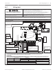
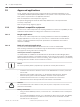
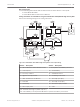
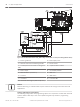
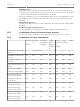
Table Of Contents
- Title Page
- Table of Contents
- Certifications, approvals, listings, and safety
- Introduction
- System overview
- Installation checklist
- Control panel installation
- Power supply
- Telephone communications
- IP communications
- Keypads, keyswitches, keyfobs and transmitters
- Keypads
- B915 Basic Keypad
- B920 Two-line Alphanumeric Keypad
- B921C Two-line Capacitive Keypad with Inputs
- B930 ATM Style Alphanumeric Keypad
- B942 Touch Screen Keypad
- Shortcuts and custom functions
- Address settings
- Supervision
- Installation and control panel wiring (keypads)
- Sensor loops overview and wiring (B921C/B942/B942W only)
- Output wiring (B942/B942W only)
- Troubleshooting
- Keyswitches
- RADION keyfobs and Inovonics pendant transmitters
- Keypads
- On-board outputs
- Off-board outputs
- On-board points
- Off-board points
- Wireless modules
- Access control
- Program and test the control panel
- Control panel board overview
- System wiring diagrams
- Approved applications
- Keypad Installer menu
- [1] Program menu
- [1] Reporting > [1] Phone menu parameters
- [1] Reporting > [2] Network menu parameters
- [1] Reporting > [3] Routing menu parameters
- [1] Reporting > [4] Personal Note menu parameters
- [2] Network > [1] Ethernet > (choose the bus module or on-board) > [1] Module Parameters menu
- [2] Network > [1] Ethernet > (choose the bus module or on-board) > [2] Address Parameters menu
- [2] Network > [1] Ethernet > (choose the bus module or on-board) > [3] DNS Parameters menu
- [2] Network > [2] Cellular > (choose the SDI2 cellular module or plug-in module)
- [3] RPS > [1] RPS Passcode menu parameters
- [3] RPS > [2] RPS Phone Number menu parameters
- [3] RPS > [3] RPS IP Address menu parameters
- [3] RPS > [4] RPS Port Number menu parameters
- [4] Area Options menu parameters
- [5] Keypad menu parameters
- [6] Users menu parameters
- [7] Points menu parameters
- [8] Disable Programming menu
- [2] Wireless menu
- [1] RF Point Menu> [1] Enroll Point RFID
- [1] RF Point Menu> [2] Replace Point RFID
- [1] RF Point Menu> [3] Remove Point RFID
- [2] RF Repeater Menu > [1] Add Repeater
- [2] RF Repeater Menu > [2] Replace Repeater
- [2] RF Repeater Menu > [3] Remove Repeater
- [3] RF Diagnostic Menu > [1] RF Points
- [3] RF Diagnostic Menu > [2] RF Repeater Menu
- [3] Diags menu
- [4] Serv Byp (Service Bypass) menu
- [5] Versions menu
- [6] Cloud menu
- [1] Program menu
- Specifications
- Appendix
- Back Page

Bell requirements
Use the following Rothenbuhler bell and balanced line modules with the control panel:
– UL Listed Model 5110 Bell
– UL Listed Model 4001-42 External Line Balancer
Wiring information for installations using the Rothenbuhler 5110/4001-42 High Security Bell
Refer to the following two figures for wiring information.
0.64 mm (0.25 in)
minimum distance
+
-
+
-
2
1
1
14
9
7
5
6
8
3
4
10
11
13
12
9
16
15
11
Figure 19.1: Rothenbuhler 5110 4001-42 High Security Bell to control panel wiring
Callout ᅳ Description
Callout ᅳ Description
1 ᅳ Self-contained UL listed vibration sensor 9 ᅳ D122/D122L Dual Battery Harness
2
2 ᅳ Control panel 10 ᅳ D126 Battery
3 ᅳ Accessory modules 11 ᅳ D8108A Enclosure
4 ᅳ High line security module 12 ᅳ Proximity/control unit
5 ᅳ 4001-42 Balanced Line Module 13 ᅳ Normally open (NO)
6 ᅳ 5110 Bell 14 ᅳ Normally closed (NC)
7 ᅳ D133 Relay 15 ᅳ End-of-line (EOL) resistor
8 ᅳ Alarm input point
1
16 ᅳ Safe
1
Use Terminals 1 through 8. (Select only one.)
2
Use a D113 Battery Lead Supervision Module to supervise the battery connections
.
Control Panel
Approved applications | en 93
Bosch Security Systems, Inc. Installation and System Reference Guide 2016.05 | 14 | F.01U.287.180