TC9217MM-W, TC9220MM-W, TC9227MM-W Instruction Manual EN Monitor Mounts 1 of 11 ISSUED: 06-25-99 SHEET #: 039-9003-8 02-08-05
EN | 2 TC9217MM-W, TC9220MM-W, TC9227MM-W | Instruction Manual | MONITOR MOUNT COMPATIBILITY CHART For Bosch LTC Series Monitors Bosch Monitor Model No.
Installation and Assembly BOSCH Monitor Wall Mounts R BOSCH TC9220MM-W 21" 27" TC9227MM-W IMPORTANT! Read entire instruction sheet before you start installation and assembly. IMPORTANT! If attaching a VCR Mount carefully study both product instruction sheets before assembly. The interface bracket (included with the VCR Mount) must be attached during monitor mount assembly to avoid disassembly later.
Attach support tray (A) to vertical support arms (P) as shown. Note: Choose the square hole which aligns closest with the center of gravity mark on the TV (as determined in step 1). Attach anti-rollout hooks (R) as shown using M6 screws (Z) and retainer bars (Y). Note: Extruded side of retainer bar (Y) goes towards anti-rollout hook (R). Hand tighten only.
For Wood Stud Walls drill three 5/32" (4 mm) dia. holes to a minimum depth of 2.5" (64 mm) into stud center. Attach wall arm (W) using three #14 x 2.5" (6 mm x 65 mm) wood screws (V). WARNING • Tighten wood screws so wall arm is firmly attached, but do not tighten with excessive force! Overtightening can cause stress damage to wood screws, greatly reducing their holding power. Tighten to 80 in • lb (9 N.M.) maximum torque.
WARNING • When installing BOSCH wall mounts on cinder block, verify that you have a minimum of 1-3/8" of actual concrete surface in the hole to be used for the concrete anchors. Do not drill into mortar joints! Be sure to mount in a solid part of the block, generally 1" minimum from the side of the block. Cinder block must meet ASTM C-90 specifications.
Note: Slots in corners of top clamps (Q) and corners of vertical support arms (P) allow for the installation of safety belt (model ACC 666, sold separately). If using this belt, install it now. DETAIL 1 Q Q Q DETAIL 2 R Z R R Q P A R P P K Position TV onto support tray (A). Position anti-rollout hooks (R) against front edge of TV. WARNING • Each anti-rollout hook (R) should have at least 1/4” of surface contact with the front of the TV.
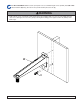
S T F O S DETAIL 3 (BOTTOM VIEW) When attaching the horizontal support (S) to wall arm or ceiling plate, carefully thread retaining collar (O) onto end of flush mount (T) tube (or extension column). Tighten at least four complete turns ending with one of the small threaded holes aligned with slot in the end of flush mount tube (T) (or extension column). Insert and tighten one M5 screw (F). WARNING • Set screw (F) is self tapping and may be hard to get started but is essential to this installation.
Parts List A1 A2 A3 B C E F G H I J K M N O P Q R S T U V W X Y Z AA BB CC Description left end support tray right end support tray center support tray 5/16 - 18 x 1/2" carriage bolt 5/16-18 washer/nut combo M10-1.5 x .7 flange nut M5 x .8 x 10 mm screw uni-clip #10 x 3/4" particle board screw #10 flat washer M10 socket head lock/flat washer combo screw M10 serrated flange head screw fiber washer - large inside dia. fiber washer - small inside dia.
GENERAL WALL MOUNT KIT SPECIFICATIONS Mount TV/Monitor Support Tray Depth (D) Model Number TC9217MM-W TC9220MM-W Product BOSCH rated when attached to...
of 12 ISSUED: 06-25-99 SHEET #: 039-9003-8 02-08-05
Americas Bosch Security Systems 130 Perinton Parkway Fairport, New York, 14450, USA Phone: +1 (585) 223 4060 Fax: +1 (585) 223 9180 E-mail: security.sales@us.bosch.com www.boschsecurity.us Europe, Middle East, Africa Bosch Security Systems B.V. P.O. Box 80002 5600 JB Eindhoven, The Netherlands E-mail: ema.securitysystems@bosch.com http://www.boschsecurity.com Asia-Pacific Bosch Security Systems Pte Ltd 38C Jalan Pemimpin Singapore 577180, Singapore Phone: +65 319 3488 Fax: +65 319 3499 E-mail: sg.