FOR MODELS: SHI 4302 6802 6806 4306 6805 BOSCH Dishwasher Repair Manual Effective: December 1, 1998 SHU 3002 3012 4002 4016 4026 4302 4312 5302 5305 5312 5315 6802 6806 3006 3016 4006 4022 4036 4306 4316 5304 5306 5314 5316 6805 4303 4803 SHV BSH Home Appliances 2800 South 25th Avenue Broadview, Illinois 60153 1st Edition/Rev.
Introduction This Repair Manual is designed to assist you in the evaluation, diagnosis and repair of the current SHI, SHU and SHV model dishwasher series. To better understand these appliances, their operation and construction we suggest that you read this manual thoroughly before attempting any repairs. All information is current at the time of printing.
H 1 Table of Contents Description Page Section 1 . . . . . . . . . . . . . . . . . . . . . . . . . . . . . . . . . . . . . . . . . . . . . . . . . . . . . . . . . . . . . . . 3 Warranty / Technical Specifications . . . . . . . . . . . . . . . . . . . . . . . . . . . . . . . . . . . . . . . . . . . . . . . . . 4 Model / Serial Number Location . . . . . . . . . . . . . . . . . . . . . . . . . . . . . . . . . . . . . . . . . . . . . . . . . . . . 5 Product Overview . . . . . . . . . . . . . . . . . . . . .
H 2 Table of Contents SERVICE REMINDER . . . . . . . . . . . . . . . . . . . . . . . . . . . . . . . . . . . . . . . . . . . . . . . . . . . 42 Description Page Section 6 . . . . . . . . . . . . . . . . . . . . . . . . . . . . . . . . . . . . . . . . . . . . . . . . . . . . . . . . . . . . . . 43 Left Side Access . . . . . . . . . . . . . . . . . . . . . . . . . . . . . . . . . . . . . . . . . . . . . . . . . . . . . . . . . . . . . . . 44 Left Side Components . . . . . . . . . . . . . . . . . . . . . .
H 3 Section 1 Description Page Warranty / Technical Specifications . . . . . . . . . . . . . . . . . . . . . . . . . . . . . . . . . . . . . . . . . . . . . . . . . 4 Model / Serial Number Location . . . . . . . . . . . . . . . . . . . . . . . . . . . . . . . . . . . . . . . . . . . . . . . . . . . . 5 Product Overview . . . . . . . . . . . . . . . . . . . . . . . . . . . . . . . . . . . . . . . . . . . . . . . . . . . . . . . . . . . . . 6 – 7 Notes . . . . . . . . . . . . . . . . . . . . . . . . . . .
H 4 Warranty / Technical Specifications Warranty 1st Year 2nd Year 3rd – 5th Year 3rd – 5th Year Parts & Labor. Parts only. Electronic Boards, parts only. Racks, parts only. This does not include rack wheels; silverware baskets or plastic shelving. Lifetime Stainless Steel. Must receive a special authorization before attempting any repairs or replacement. Cosmetic items, Facia and Door Panels are only warranted against manufacturing defects.
H 5 Model / Serial Number Location Fig. 1-1 Fig. 1-2 Located on the right hand side of the Inner Door is the Model and Serial number tag, Fig. 1-1. The Model and Serial numbers can be found on the left side of the tag within the black outline box, Fig. 1-2. The Model Number for this unit is SHU 5312 UC/U06. Located just under the Model Number is the ten-digit Serial Number. The Serial Number for this unit is FD 7801 123456.
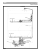
H 6 Product Overview The Bosch dishwasher utilizes a two motor system with separate Circulation and Drain Motors, and a Flow Through Heater controlled by a Flow Switch and NTC Thermistor. With some models also having the advanced logic feature of an Aqua Sensor turbidity measuring devise, Fig. 2-1. • A two motor system allows each motor to be designed for a single function, thus reducing overall size and energy consumption. While also reducing operating noise.
H 7 Product Overview Overhead Spray Coupling Upper Spray Arm Feed Tube Lower Spray Arm Aqua Sensor Sump Fig.
H 8 Notes
H 9 Section 2 Description Page Operation, SHU 3002 / 3006 / 3012 / 3016 / 4002 / 4006 / 4016 / 4022 / 4026 / 4036 . 10 Cycle Chart . . . . . . . . . . . . . . . . . . . . . . . . . . . . . . . . . . . . . . . . . . . . . . . . . . . . . . . . . . . . . . . . . . . . 11 Operation, SHI 4302 / 4306 SHU 4302 / 4306 / 4312 / 4316 . . . . . . . . . . . . . . . . . . . . . . . . . . . . . . . . . . . . . . . 12 Cycle Chart . . . . . . . . . . . . . . . . . . . . . . . . . . . . . . . . . . . . . . . . . . . .
H 10 Operation SHU 3002/3006/3012/3016/4002/4006/4016/4022/4026/4036 Fig. 3-1 Fig. 3-2 The SHU 30** and 40** are both mechanical units that operate using a basic Timer and Selector Switch. TO OPERATE EITHER MODEL, (a SHU 4006 is shown): Fig. 3-2. First select a cycle by pushing the corresponding Cycle Button in. The Cycle Button remains in the indented position until another cycle is chosen. Now, depress the On/Off Button until it locks in place and the On LED illuminates.
H 11 Cycle Chart SHU 3002/3006/3012/3016/4002/4006/4016/4022/4026/4036 Type of dishware e.g. china, pots/pans, Non-delicutlery, cate glasses, etc.
H 12 Operation SHI 4302/4306 SHU 4302/4306/4312/4316 Fig. 3-3 Fig. 3-4 The SHI or SHU 43** series operates using an electronic Control Unit. TO OPERATE: Fig. 3-3. First depress the On/Off Button until it locks in place. Fig. 3-4. Once the On/Off Button is depressed the LED above the previously used cycle will illuminate. To change the cycle, simply press the desired Cycle Button twice. The LED above that cycle will then illuminate.
H 13 Cycle Chart SHI 4302/4306 Type of dishware e.g. china, pots/pans, Non-delicutlery, cate glasses, etc.
H 14 Operation SHU 5302/5304/5305/5306/5312/5314/5315/5316 Fig. 3-5 Fig. 3-6 The SHU 53** series operates using an electronic Control Unit. TO OPERATE: Fig. 3-5. First depress the On/Off Button until it locks in place. Fig. 3-6. Once the On/Off Button is depressed the LED above the previously used cycle will illuminate. To change the cycle, simply press the desired Cycle Button twice. The LED above that cycle will then illuminate.
H 15 Cycle Chart SHU 5302/5304/5305/5306/5312/5314/5315/5316 Type of dishware e.g. china, pots/pans, Non-delicutlery, cate glasses, etc.
H 16 Operation SHI/SHU 6802/6805/6806 Fig. 3-7 Fig. 3-8 The SHI / SHU 68** series operates using an electronic Control Unit. TO OPERATE: Fig. 3-7. First depress the On/Off Button until it locks in place. Fig. 3-8. Once the On/Off Button is depressed the LED above the previously used cycle will illuminate. To change the cycle, simply press the desired Cycle Button twice. The LED above that cycle will then illuminate. The Cycle Countdown will display an approximate run time for the cycle chosen.
H 17 Cycle Chart SHI/SHU 6802/6805/6806 Type of dishware e.g. china, pots/pans, Non-delicutlery, cate glasses, etc.
H 18 Notes
H 19 Section 3 Description Page Rack System . . . . . . . . . . . . . . . . . . . . . . . . . . . . . . . . . . . . . . . . . . . . . . . . . . . . . . . . . . . . . . 20 – 21 Interior Features . . . . . . . . . . . . . . . . . . . . . . . . . . . . . . . . . . . . . . . . . . . . . . . . . . . . . . . . . . . 22 – 25 Detergent / Rinse-Agent Dispenser . . . . . . . . . . . . . . . . . . . . . . . . . . . . . . . . . . . . . . . . . . . . . . . . 26 Washability / Drying . . . . . . . . . . . . . . . . .
H 20 Rack System Rack configurations for individual dishwasher models will vary. However, all Racks are constructed from a steel wire grid with a gray nylon outer covering. Note: Racks may discolor due to the water supply or types of food remaining on the dishes. We recommend that a vinegar wash be used to assist in removing these stains. Start the unit, and let run approximately ten minutes, then pour in two cups of white vinegar and let the unit complete the cycle, repeat if necessary. Fig. 4-1 Fig.
H 21 Rack System Fig. 4-4 Fig. 4-5 Attached to the Upper Rack is the Upper Spray Arm Assembly. The Upper Spray Arm can be removed from the Upper Spray Arm Assembly for cleaning or replacement by turning the Arm Nut counter-clockwise, Fig. 4-4. And then bringing the Arm down and off the Arm Assembly, Fig. 4-5.
H 22 Interior Features 1 2 2 7 3 4 6 5 Fig. 5-1 Interior features for all model dishwasher covered in this repair manual are identical. Those features include: 1. 2. 3. 4. 5. 6. 7. Strike Plate. The Strike Plate is in a fixed position and cannot be adjusted. Upper Rack Rails and Guide Rollers.
H 23 Interior Features Fig. 5-2 The Upper Rack Rails are made of stainless steel with a plastic end cap. Fig. 5-3 To remove the Rail, disengage the End Cap by applying outward pressure to the Cap’s top tab, unclipping it from the Rail. Then slide the Rail out from the Guide Rollers. Fig. 5-4 The Upper Rack Guide Rollers are permanently attached to the Tank and cannot be removed or repaired. Fig. 5-5 The Door Gasket is press fit into a channel molded around the Tank. Fig.
H 24 Interior Features Water Level Fig. 5-7 Fig. 5-8 Fig. 5-9 Fig. 5-10 2 1 Fig. 5-11 Fig.
H 25 Interior Features Fig. 5-7 The operating water level of the dishwasher is at approximately the upper edge of the filter basket. Fig. 5-8 The Lower Spray Arm is press fit into the Feeder Tube Socket. To remove the Arm, grasp the Arm Hub and pull up until the Arm disengages from the Socket. The Arm or Arm Socket can now be checked for debris. Fig. 5-9 The Filter Basket is removed by turning it ninety degrees counter-clockwise. Fig. 5-10 Then lift it out for cleaning.
H 26 Detergent / Rinse-Agent Dispenser Located on the Inner Door is the Detergent / Rinse Agent Dispenser, Fig. 6-1. The Dispenser Housing is one assembly containing three individual components. Rinse Agent Dispenser. Detergent Cup. Steam Vent. Note: Mechanical operation and removal of the Dispenser is shown in Section 4. Fig. 6-1 To fill or adjust the Rinse Agent Dispenser, open the Rinse Agent Door by pulling up on the Door Latch. 1 The Dosage Meter, item 1, is now visible.
H 27 Washability / Drying WASHABILITY There are four factors that play a critical role in Washability: Time, Temperature, Water and Detergent. It is important when attempting to determine the cause of a Washability complaint that all four factors be considered and tested. Time: The duration of the program is accurate (see cycle chart). Temperature: The wash and rinse temperatures are within the desired range (see cycle chart). Water: The unit is filling with the correct amount of water (Section 3, Fig.
H 28 Service Reminder From this point in the manual only the technical features and components of the SHU 5312 will be demonstrated. However, due to the overwhelming similarities between the model SHU 5312 and the remaining Bosch Dishwasher line, you will be able to easily diagnose and repair all current Bosch model SHU, SHI and SHV Dishwashers.
H 29 Section 4 Description Page Outer Door Removal . . . . . . . . . . . . . . . . . . . . . . . . . . . . . . . . . . . . . . . . . . . . . . . . . . . . . . . . . . . . 30 Door Components . . . . . . . . . . . . . . . . . . . . . . . . . . . . . . . . . . . . . . . . . . . . . . . . . . . . . . . . . . . . . . 31 Dispenser Operation . . . . . . . . . . . . . . . . . . . . . . . . . . . . . . . . . . . . . . . . . . . . . . . . . . . . . . . . . . . . 32 Dispenser Removal . . . . . . . . . . . . . . .
H 30 Outer Door Removal Fig. 7-1 Fig. 7-2 To remove the Outer Door, open the door and remove the six T-20 Torx screws located three on each side of the Inner Stainless Door, Fig. 7-1. Return the door back to its upright position, and bring the bottom of the Door Panel out toward you, then slide the top of the panel down and out from under the Facia Panel, Fig. 7-2. As the Outer Door is being removed, the left or right Door Guards may shift or fall out of place, Fig. 7-3. Fig.
H 31 Door Compoments 7 2 6 1 3 5 4 4 8 9 9 Fig. 7-5 Once the Outer Door has been removed the following components become visible. 1. 2. 3. 4. 5. 6. 7. Dispenser Assembly Condensation Tube Upper Wiring Harness Door Guards Door Seal Bituminious Insulation Cloth Fiber Insulation Also note the Toe Kick, item 8, and the Toe Kick Mounting Screws, item 9.
H 32 Dispenser Operation 2 1 Fig. 8-1 The Dispenser Assembly operates via a PTC Actuator (wax motor), item 1. When voltage is applied to the Actuator it advances a Combination Lever, item 2. Fig. 8-2 …and bring the Actuator out from the Dispenser. Please note: The Combination Lever cannot be replaced individually, but only as part of a new Dispenser Assembly. The Combination Lever allows the Soap Door to open, and later in the cycle dispenses the Rinse Agent.
H 33 Dispenser Removal Fig. 8-5 Fig. 8-6 If required, the Dispenser Assembly can be replaced as a complete unit. TO REMOVE: First remove the: Upper Rack (Section 3, Fig. 4-3). Wiring Connectors for the PTC Actuator, Reed Switch and Condensation Tube. The Condensation Tube is inserted into the right side of the Dispenser with a gasket seal, and press fit along the right side of the Inner Stainless Steel Door.
H 34 Facia Assembly IMPORTANT SERVICE NOTE: The Facia Assembly cannot be removed unless the Outer Door is removed first. See section 4, Fig. 7-1. FACIA ASSEMBLY REMOVAL: After removing the Outer Door, remove the six T-20 Torx screws securing the Facia Assembly to the Inner Stainless door, Fig. 9-1. Fig. 9-1 Fig. 9-2 Fig. 9-3 With the screws removed, bring the Facia Assembly down cradling it so as not to scratch the Facia Console.
H 35 Facia Assembly With the Facia Assembly removed from the unit, it can be further separated into two assemblies. To separate, release the four locking tabs and bring the Facia Frame up from the Facia Console, Fig. 9-4. Fig. 9-4 The Facia Frame houses three components: 1 3 2 Item 1, On/Off Switch. Item 2,Door Latch Assembly. Item 3,Control Unit. Note: The Facia Console or Program Buttons can be replaced at this time. Fig. 9-5 ON/OFF SWITCH REMOVAL: 1 2 Bend the single tab up, item 1.
H 36 Notes
H 37 Section 5 Description Base Components – Front Accessible: Page Electrical Connection . . . . . . . . . . . . . . . . . . . . . . . . . 38 Circulation Motor Capacitor . . . . . . . . . . . . . . . . . . . 38 Leveling Legs . . . . . . . . . . . . . . . . . . . . . . . . . . . . . . . 39 Water Valve . . . . . . . . . . . . . . . . . . . . . . . . . . . . . . . . . 39 Drain Motor . . . . . . . . . . . . . . . . . . . . . . . . . . . . 40 — 41 Notes . . . . . . . . . . . . . . . . . . . . . . . . . . .
H 38 Base Components – Front Accessible = 3 7 6 2 8 5 9 = 4 1 3 Fig. 10-1 Service note: 2 To gain access to the Front Accessible Lower Components remove the Toe Kick. Also, for better visibility it is strongly recommended that the Outer Door be removed as well. The Front Accessible Lower Components consist of the following items. 1. 2. 3. 4. 5. 6. 7. 8. 9. Electrical Connection. Circulation Motor Capacitor. Front Leveling Legs. Model and Serial number tag.
H 39 Base Components – Front Accessible 1 2 Fig. 10-3 Fig. 10-4 The front Leveling Legs can be adjusted by inserting a regular tipped screwdriver into the foot slot and turning the leg in the desired direction. The Rear Leg Adjustment Screw, item 1, allows the single Rear Leveling Leg to be adjusted from the front of the unit. Turning the screw clockwise will extend the leg, and counter-clockwise retracts it. For convenience an additional Serial Number Tag, item 2, is located on the Base. Fig.
H 40 Base Components – Front Accessible Service note: To provide the required access that will allow the Drain Motor to be replaced, the Lower Access Panel must be removed, and as previously mentioned the Outer Door Panel should also be removed. 1 To remove the Lower Access Panel, Fig. 10-7, item 1, remove the two T-20 Torx screws located in the left and right corners of the panel. Fig. 10-7 As demonstrated in Figs.
H 41 Base Components – Front Accessible 1 2 1 B 2 3 A Cut Away View Fig. 10-9 To remove the Drain Motor, item 1, first remove the Sump Fill Hose, item 2, by pulling it out from the Sump and side inlet connections (see Fig. 10-10) Fig. 10-10 This cut away view shows: Item 1, Drain Motor. Item 2, Drain Motor Locking Tab. Item 3, the Sump Fill Hose and its two connection points A and B. Fig. 10-11 Fig. 10-12 Fig.
H 42 Service Reminder From this point forward, all service procedures demonstrated in the remainder of this repair manual, will require the dishwasher to be disconnected and removed from the cabinet for servicing.
H 43 Section 6 Description Page Left Side Access . . . . . . . . . . . . . . . . . . . . . . . . . . . . . . . . . . . . . . . . . . . . . . . . . . . . . . . . . . . . . . . 44 Left Side Components . . . . . . . . . . . . . . . . . . . . . . . . . . . . . . . . . . . . . . . . . . . . . . . . . . . . . . . . . . . 45 Water Inlet / Discharge System – Operation . . . . . . . . . . . . . . . . . . . . . . . . . . . . . . . . . . . . .46 – 47 Water Inlet / Discharge System – Removal . . . . . . . . . . . .
H 44 Left Side Access LEFT SIDE PANEL REMOVAL: Remove the two T-20 Torx screws located on the top and bottom of the Left Trim Strip, Fig. 11-1, and then slide the Trim Strip up and off the unit. Figs. 11-2 and 11-3 The Side Panel is press fit onto the Front and Rear Corner Blocks of the dishwasher. To remove the panel, gently lift up on the front corner disengaging it from the Front Corner Block, arrow A.
H 45 Left Side Components 1 1 2 4 3 6 5 7 8 Fig. 11-4 With the Left Side Panel removed you now have access to the following components: 1. 2. 3. 4. 5. 6. 7. 8. Corner Blocks. Cloth Fiber Insulation Panel. Drain Hoses. Water Chamber. Inlet Water Line. Water Level Housing Assembly. Sump Fill Hose. Left Hinge.
H 46 Water Inlet / Discharge System – Operation 6 4 7 5 1 2 3 8 9 Fig. 12-1 Normal Fill Over Fill Base Float Fig. 12-2 Fig. 12-3 Fig.
H 47 Water Inlet / Discharge System – Operation WATER SYSTEM OPERATION: Fig. 12-1 is a close up view of the complete Water Systems. FILLING NORMAL OPERATION (Fig. 12-2) Fresh water is brought in by the Water Valve and through the Inlet Water Line, item 3. The incoming water is then directed into the Water Level Housing Assembly, item 4, and then on to the Sump via the Sump Fill Hose, item 8.
48 H Water Inlet / Discharge System – Removal 1 Fig. 12-7 The Water Level Switch and Diaphragm are replace as one assembly. To replace, bend the small retaining tab out away from the assembly. Fig. 12-8 Then remove the wiring connector and slide the assembly up and out from the Water Level Housing. Fig. 12-9 To replace either Drain Hose, first remove the Drain Hose retaining clip. Fig. 12-10 Then bring the hose down and out from the Water Chamber.
H 49 Section 7 Description Page Right Side Access . . . . . . . . . . . . . . . . . . . . . . . . . . . . . . . . . . . . . . . . . . . . . . . . . . . . . . . . . . . . . . 50 Right Side Components . . . . . . . . . . . . . . . . . . . . . . . . . . . . . . . . . . . . . . . . . . . . . . . . . . . . . . . . . 51 NTC Operation . . . . . . . . . . . . . . . . . . . . . . . . . . . . . . . . . . . . . . . . . . . . . . . . . . . . . . . . . . . . . . . . . 52 NTC Removal . . . . . . . . . . . . . . . . .
H 50 Right Side Access Fig. 13-1 Fig. 13-2 RIGHT SIDE PANEL REMOVAL: Remove the two T-20 Torx screws located on the top and bottom of the Left Trim Strip, Fig. 13-1, and then slide the Trim Strip up and off the unit. To remove the panel, refer to Section 6, Figs. 11-2 and 11-3.
H 51 Right Side Components 5 1 3 4 2 Fig. 13-3 With the Right Side Panel removed, you now have access to the following components. 1. 2. 3. 4. 5. Circulation Pump / Motor. Base Wiring Connectors. Flow Switch. Heater Assembly. NTC. COMPONENT EXPLANATION: Circulation Pump / Motor. The Circulation Pump / Motor can be replaced from the right side by following the same access procedures for removal of the NTC outlined in the remainder of this section, and then by following the steps in Section 8, Figs.
H 52 NTC Operation Fig. 14-1 Located on top of the Heater Assembly is the NTC (Negative Temperature Coefficient), Fig. 14-1. The NTC uses resistance to control wash and rinse water temperature and is connected with two green leads. As water temperature increases, the NTC records the decrease in resistance. The Control Unit Logic Board measures this resistance change and allows the program to advance once the correct temperature (resistance level) is reached.
H 53 NTC Removal To replace the NTC, first remove the Right Side Panel, Outer Door and Toe Kick, Fig. 14-2. Then, remove the two Front Base Mounting Screws, Fig. 14-3. And the single Rear Base Mounting Screw, Fig. 14-4. Fig. 14-2 Fig. 14-3 Fig.
H 54 NTC Removal Next, remove the Hinge Cover… Fig. 14-5 and, unhook the Pulley Arm from the Hinge by lifting it up… Fig. 14-6 and then off the Hinge. Fig.
H 55 NTC Removal Now, from inside the dishwasher remove the Lower Spray Arm, Filter Basket and Screen, then remove the two screws that attach the Feeder Tube to the Sump, item 1. And the two Sump Clamps, item 2. 1 2 Fig. 14-8 With all steps complete, bring the Tank up from the Base and insert a block in the rear of the unit between the Tank and the Base. Fig. 14-9 With the block in place you now have the required access to replace the NTC.
H 56 NTC Removal Fig. 14-11 Fig. 14-12 As demonstrated in Figs. 14-11 and 14-12, raising the Tank provides the necessary access space required to remove either the NTC or the Circulation Pump / Motor. Service note: When re-seating the Tank make sure to check that it is inserted squarely back into the pump and seated properly.
H 57 NTC Removal 2 1 The NTC is held in place by two locking tabs, items 1 and 2. To remove the NTC from the Heater Assembly, unhook the front tab, item 1, and lift the NTC up slightly on that side, holding the tab open as you lift. Fig. 14-13 Cut Away View Then unhook the rear tab, item 2, holding it open, while you slide the NTC up and out from the Heater Assembly. 1 2 Fig.
H 58 Notes
H 59 Section 8 Description Page Tank Removal . . . . . . . . . . . . . . . . . . . . . . . . . . . . . . . . . . . . . . . . . . . . . . . . . . . . . . . . . . . . . 60 – 62 Base Components . . . . . . . . . . . . . . . . . . . . . . . . . . . . . . . . . . . . . . . . . . . . . . . . . . . . . . . . . . . . . . 63 Circulation Pump / Motor Removal . . . . . . . . . . . . . . . . . . . . . . . . . . . . . . . . . . . . . . . . . . . . . . . . . 64 Circulation Pump / Motor Assembly . . . . . . . . . . .
H 60 Tank Removal Fig. 15-1 Fig. 15-2 In order to gain full access to the Circulation Pump / Motor, Heater Assembly and Aqua Sensor the Tank must be removed. 1 To remove the Tank, start by removing the Outer Door, Left and Right Side Panels, and Toe Kick, leaving the unit as shown in Fig. 15-1. Next, disconnect the Upper Wiring Harness from the Control Unit and On/Off Switch, and then bring the harness off its mounting point on the Condensation Tube, Fig. 15-2.
H 61 Tank Removal Then on both the left and right sides, remove the Hinge Covers… Fig. 15-4 and unhook the Pulley Arms from both Hinges by lifting them up… Fig. 15-5 and then off the Hinges. Fig.
H 62 Tank Removal 1 2 Fig. 15-7 Fig. 15-8 Fig. 15-7 Now on both the left and right sides remove the T-20 Torx Tank Mounting Screws, item 1, and the Door Hinge Pivot tab, item 2. Fig. 15-8 To remove the Door Hinge Pivot Tab, insert your T-20 Torx bit into the Tab and bring the screwdriver down releasing the tab. Service note: The tab is a press fit, and will simply snap into position when replaced. Fig.
H 63 Base Components 3 4 2 1 Fig. 16-1 The Tank can now be removed from the Base. Service note: Once removed, lay the Tank on its back so as not to damage the tank bottom. When reseating the Tank make sure to check that it’s inserted squarely back into the Sump and seated properly. With the Tank removed you now have access to the following components: 1. 2. 3. 4.
H 64 Circulation Pump / Motor Removal 2 1 Fig. 16-2 Fig. 16-3 1 3 4 Fig. 16-4 Fig.
H 65 Circulation Pump / Motor Assembly Fig. 16-6 Fig. 16-7 CIRCULATION PUMP / MOTOR REMOVAL: Disconnect the four wire leads, then grasp the Circulation Motor and turn clockwise a quarter turn until the Motor stops, Fig. 16-2. Now, remove the Motor / Rear Pump Assembly from the Front Pump Housing, Fig. 16-3. Note: The Front Pump Housing remains in place when the Motor is removed, Fig.16-3, item 1. With the Motor / Rear Pump Assembly removed from the unit, separate the Motor from the Rear Pump Assembly.
H 66 Heater Assembly Removal 3 1 4 2 Fig. 16-8 Fig. 16-9 Aqua Sensor NTC Flow Through Heater Upper Spray Arm Flow Switch Lower Spray Arm Circulation Motor / Pump Impeller Cover Drain Motor Fig.
H 67 Heater Assembly 2 3 1 4 5 6 7 Fig. 16-11 Fig. 16-12 The Heater Assembly, Fig. 16-8 is a flow through design, taking water in from the Circulation Pump and then sending it out the two discharge outlets to the Upper and Lower Spray Arms, Fig. 16-10. HEATER ASSEMBLY REMOVAL: See Fig. 16-9, first remove all wiring leads and the two securing screws, item 1.
H 68 Aqua Sensor Fig. 16-13 Fig. 16-14 The Aqua Sensor turbidity measuring device, Fig. 16-13, which is available only on select models, evaluates the pre-wash water using a beam of light and a pick-up sensor. If the beam passes easily through the pre-wash water then no additional wash water is added. If the beam cannot pass through, then the pre-wash water is drained and a fresh fill is added for the main wash cycle. To replace the sensor, Fig.
H 69 Door Spring Removal The Door Springs are located on the bottom of the Base, Fig. 16-15, and operate via a Spring Cable and Reel that counter balances the weight of the Outer Door, Fig. 16-16. If a Door Panel Kit is applied to the dishwasher, the factory springs must be replaced with the heavy duty version that is provided with the panel kit. Fig. 16-15 TO REPLACE THE SPRINGS: Lay the dishwasher on its back, being careful not to damage the Drain Hose.
H 70 Notes
H 71 Section 9 Description Page Wiring Diagrams / Schematics . . . . . . . . . . . . . . . . . . . . . . . . . . . . . . . . . . . . . . . . . . Page 72 — 84 Description Diagrams Test Program . . . . . . . . . . . . . . . . . . . . . . . . . . . . . . . . . . . . . . . . . . . . . . . . . . . . . . . . . . . . . . . . . . . . 1 SHI 4302 SHI 4306 . . . . . . . . . . . . . . . . . . . . . . . . . . . . . . . . . . . . . . . . . . . . . . . . . . . . . . . . . . . . . . . . . .
H 72 Diagram 1 FUNCTION DURATION COMMENTS DRAINING 30 Seconds AQUA SENSOR CALIBRATION 65 Seconds Not used on the SHI/U 43-- FILLING Until Water Level Switch (f1) Closes. This function cannot be bypassed HEATING & CIRCULATING Until Water Temperature Reaches 150° f. Dispenser Actuator Energizes DRAINING 60 Seconds • To bypass a function: SHI/U 43-- Press the SCRUB WASH button SHI/U 53--/68-- Press the REGULAR WASH button.
H a1 L1 4 3 1 e6 u6 4 2 b a b b u4 b a a a u5 u3 b2 3 a u2 u8 b a b 5 b1 6 4 1 f1 2 161˚F 1 2 b3 140˚F 4 f4 h1 f3 e5 F 2 s2 permanent split capacitor motor 1 4 L PTC A2 1M r1 1M m3 m1 1M 1M m2 185˚F N e0 N 2 1 2 current path f5 1 3 4 5 6 Symbol Key a1 A2 e0 e5 e6 f1 f3 f4 f5 h1 m1 m2 m3 r1 s2 u– MAIN SWITCH 2 ACTUATOR (Dispenser) 7 DOOR SWITCH 3 FLOW SWITCH 11 FLOAT SWITCH 7 WATER LEVEL SWITCH 5 THERMOSTAT 140˚F 9 THERMOSTAT 161˚F 6 current
3b 3a 3 b. b. b. b. b. b.
H PRE-WASH 1 T I 2 M 3 E 4 R 5 6 7 8 PRE-RINSE RINSE W/ HEAT DRYING Timer Stop Circulation Motor Actuator Heating Element Drain Motor Water Solenoid Thermostat 161˚ Thermostat 140˚ Drain Motor Timer Motor 161˚ Thermostat Bypass TIME IN SECONDS TIMER POSITION OPERATION 30 30 f1+5 f1+55 60 60 30 30 (5) f1+5 f1+50 60 60 60 30 30 f1+5 f1+55 60 60 180 f3/f4+5 f3+5 230 30 30 60 60 f1+5 f1+55 240 30 30 f1+5 f1+55 60 60 f3+5 55 60 f4+5 45 5 5 60 240 240 240 60 60 60 60 11 12 13 14 15 16 17 18 19 1 2 3 4 5
4 3 1 e6 u6 4 2 b a b b u3 a u4 b a b2 3 a u2 u8 a u5 b a b b1 5 6 4 1 f1 2 b3 2 161˚F 1 140˚F 4 f4 h1 f3 e5 F 4 L PTC A2 1M permanent split capacitor motor 1 2 s2 76 Diagram 5 a1 L1 r1 1M m3 m1 1M 1M m2 185˚F N e0 N 2 1 2 current path f5 1 3 4 5 6 Symbol Key Symbol Key a1 A2 e0 e5 e6 f1 f3 f4 f5 h1 m1 m2 m3 r1 s2 u– MAIN SWITCH 2 ACTUATOR (Dispenser) 7 DOOR SWITCH 3 FLOW SWITCH 11 FLOAT SWITCH 7 WATER LEVEL SWITCH 5 THERMOSTAT 140˚F 9 THER
3b 3a 3 b. b. b. b. b. b.
6 7 8 RINSE W/ HEAT DRYING Timer Stop Circulation Motor Actuator Heating Element Drain Motor Water Solenoid Thermostat 161˚ Thermostat 140˚ Drain Motor Timer Motor 161˚ Thermostat Bypass TIME IN SECONDS TIMER POSITION OPERATION 30 30 f1+5 f1+55 60 60 30 30 (5) f1+5 f1+50 60 60 60 30 30 f1+5 f1+55 60 60 180 f3/f4+5 f3+5 230 30 30 60 60 f1+5 f1+55 240 30 30 f1+5 f1+55 60 60 f3+5 55 60 f4+5 45 5 5 60 240 240 240 60 60 60 60 11 12 13 14 15 16 17 18 19 1 2 3 4 5 6 7 8 9 10 11 12 13 14 15 16 17 18 19 20 21
1 f2-f4 NTC l4 1 1 1 7 H e3 6 1 3 12.6-1/2 X2 1 2 1 e0 a1 X1 12.5 12.9 12.8 Control Unit 1 12.1-1 N 2 12.1-2 3 4 12.1-3 5 6 L1 12.7-1 12.2 1 12.4 2 8 12.4-1 7 3 12.4-2 185˚F L s2 1 A1 A2 12.
.1 .2 2 1 1 2 .4 8 7 6 5 4 3 2 1 .6 2 1 .5 4 GNYE-PE-1 2 GNYE-r1 1 GNYE-m2 GNYE-PE-4 80 Ground – PE .7 3 2 1 Diagram 9 Control Unit – l2 .5 7 6 5 4 3 2 1 .9 1 2 3 4 5 6 1 WHRD-l2.1-1 WHRD-e5-1 WH-l1-N GYBK-l2.7-1 BK-l1-L1 WH-l2.1-3 WH-l6-2 WH-l2.4-8 Water Level Switch – f1 4 BN-l5-5 BN-l5-6 BN-l5-7 Wiring Connectors – I5 & I6 1 NTC – f2 & f4 / Thermostat – f5 RD-e6-1 1 BN-l5-1 BN-l5-2 BK-l2.1-2 GYBK-a1-3 RD-l6-1 BU-l6-6 BU-l6-7 BU-l6-8 BU-l6-9 WH a1-6 WH l6-3 WH a1-5 BK-l2.
Reed Switch – e3 .7 .1 .2 3 2 1 2 1 N 1 2 .4 .6 8 7 6 5 4 3 2 1 .5 7 6 5 4 3 2 1 .9 Ground – PE 4 GNYE-PE-1 2 GNYE-r1 1 GNYE-m2 GNYE-PE-4 YE-l2.6-2 .5 2 1 H Control Unit – l2 YE-l2.6-1 S e0 1 BN-l5-5 BN-l5-6 BN-l5-7 BN-l5-1 BN-l5-2 YE-e3 YE-e3 BK-l2.1-2 GYBK-a1-3 RD-l6-1 BU-l6-6 BU-l6-7 BU-l6-8 BU-l6-9 WH a1-6 WH l6-3 BU-A2 BU-A2 WH a1-5 BK-l2.
.7 On/Off Switch – a1 Door Switch – e0 .1 .2 3 2 1 2 1 N 1 2 .4 .6 8 7 6 5 4 3 2 1 .5 2 1 BN-l5-5 BN-l5-6 BN-l5-7 BN-l5-1 BN-l5-2 YE-e3 YE-e3 RD-e6-1 NTC BN-l4-3 BN-l4-2 BN-l4-1 f2-f4 4 1 BU-l6-7 GN-l5-2 2 f5 P Actuators – A1 & A2 RD-l6-1 185˚ upper basket wash RD-r1 Water Solenoid – s2 GNYE-r1 VT-l6-6 RD-f5 WH-A1 GY-A1 WH-l6-2 RD-e6-1 A1 high limit GY-l6-3 Circulation Motor – m2 detergent WH-e6-2 BK-l6-8 WHVT-m3 Float Switch – e6 1 RD-f1-1 RD-A1 2 3 BU-l2.
f2-f4 NTC 2 4 X2 1 1M 1 2 12.6 12.7-1/2 H e3 e1 1 m2 a1 1 12.4-2 12.8 12.2-3 12.2-2 1 2 3 4 5 6 N 12.5-2 L1 Control Unit 12.3-1/2 12.4-1 12.1 1 12.4-3 3 permanent split capacitor motor 12.
Door Switch – e1 .5 .1 .2 .3 .4 1 2 3 1 2 3 1 2 1 2 3 2 1 .6 .7 .
BSH Home Appliances 2800 South 25th Avenue Broadview, Illinois 60153