LTC 9384 Series Instruction Manual EN Outdoor Camera Housings
LTC 9384 | Instruction Manual | Important Safeguards EN | 2 Important Safeguards 1. Read, Follow, and Retain Instructions - All safety and operating instructions should be read and followed before operating the unit. Retain instructions for future reference. 2. Heed Warnings - Adhere to all warnings on the unit and in the operating instructions. 3. Attachments - Attachments not recommended by the product manufacturer should not be used, as they may cause hazards. 4.
EN | 3 LTC 9384 | Instruction Manual | Safety Precautions For Indoor Product 1. Water and Moisture - Do not use this unit near water - for example, in a wet basement, in an unprotected outdoor installation or in any area classified as a wet location. 2. Object and Liquid Entry - Never push objects of any kind into this unit through openings, as they may touch dangerous voltage points or short out parts that could result in a fire or electrical shock. Never spill liquid of any kind on the unit. 3.
EN | 4 LTC 9384 | Instruction Manual | Safety Precautions Sicherheitshinweise VORSICHT: UM EINEN ELEKTRISCHEN SCHLAG ZU VERMEIDEN, IST DIE ABDECKUNG (ODER RÜCKSEITE) NICHT ZU ENTFERNEN. ES BEFINDEN SICH KEINE TEILE IN DIESEM BEREICH, DIE VOM BENUTZER GEWARTET WERDEN KÖNNEN. LASSEN SIE WARTUNGSARBEITEN NUR VON QUALIFIZIERTEM WARTUNGSPERSONAL AUSFÜHREN. Das Symbol macht auf nicht isolierte „gefährliche Spannung" im Gehäuse aufmerksam. Dies kann zu einem elektrischen Schlag führen.
EN | 5 LTC 9384 | Instruction Manual | Safety Precautions Medidas de Segurança CUIDADO: PARA REDUZIR O RISCO DE CHOQUE ELÉCTRICO, NÃO RETIRE A TAMPA (OU A PARTE POSTERIOR). NO INTERIOR, NÃO EXISTEM PEÇAS QUE POSSAM SER REPARADAS PELO UTILIZADOR. REMETA A ASSISTÊNCIA PARA OS TÉCNICOS QUALIFICADOS. Este símbolo indica a presença de "tensão perigosa" não isolada dentro da estrutura do produto, o que pode constituir risco de choque eléctrico.
LTC 9384 Series | Instruction Manual | Contents EN | 6 Table of Contents Important Safeguards . . . . . . . . . . . . . . . . . . . . . . . . . . . . . . . . . . . . . . . . . . . . . . . . . . . . . . . . . . . . . . . . . . . . . .2 1 UNPACKING . . . . . . . . . . . . . . . . . . . . . . . . . . . . . . . . . . . . . . . . . . . . . . . . . . . . . . . . . . . . . . . . . . . . .7 2 SERVICE . . . . . . . . . . . . . . . . . . . . . . . . . . . . . . . . . . . . . . . . . . . . . . . . . . . . . . . . .
EN | 7 LTC 9384 Series | Instruction Manual | Unpacking 1 UNPACKING This electronic equipment should be unpacked and handled carefully. Check for the following items: • Verify the unit model number • Verify that parts listed as follows have been included. See INSTALLATION. Hardware Kit Quantity Part Description 3 Cable Tie 2 BHCS, 1⁄4-20 x 1⁄4in. 1 BHCS, 1⁄4-20 x 5⁄8in. 1 BHCS, 1⁄4-20 x 3⁄4in. 1 BHCS, 1⁄4-20 x 1⁄2in. 1 BHCS, 1⁄4-20 x 3⁄8in. 1 BHCS, 1⁄4-20 x 11⁄4in. 2 0.4mm (0.016in.) Plastic Spacer 1 1.
EN | 8 LTC 9384 Series | Instruction Manual | Installation Maximum Camera/Lens Size: LTC 9384/xx: Accepts cameras up to 64W x 54H mm (2.5 x 2.1in.), lenses up to 67W x 75H mm (2.6 x 2.9in.), and camera/lens combinations up to 292mm (11.5in.). LTC 9384/20NT: Accepts cameras up to 64W x 54H mm (2.5 x 2.1in.), lenses up to 67W x 75H mm (2.6 x 2.9in.), and camera/lens combinations up to 355mm (14.0in.). 5.2 • • • • • • 5.3 Tools Required Flat blade screwdriver Phillips head screwdriver 5⁄32in.
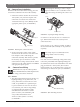
EN | 9 LTC 9384 Series | Instruction Manual | Installation 5.5 Camera/Lens Installation With the cradle removed from the housing, place the camera/lens combination into the cradle assembly. 1. Fixed Lens Cameras: Position the camera/lens 1mm (0.04in.) away from the faceplate. The camera/lens is secured to the cradle with a 1⁄4-20 button head cap screw (BHCS) and the appropriate plastic spacer (see FIGURE 2). Securely tighten all fittings to ensure a liquidtight seal.
EN | 10 LTC 9384 Series | Instruction Manual | Installation 5.6.3 Power Connections The LTC 9384 Series Housings (except the nontransformer LTC 9384/20NT version) allow the use of 24VAC cameras, regardless of the supply voltage to the housing. This is achieved via transformer in the housing. The transformer's primary supply power varies, depending on the model of housing, (see Section 5.1 Model Designation).
EN | 11 LTC 9384 Series | Instruction Manual | Installation To Heater/Defogger For 24 Volt Cameras: 1. Installing a 24 volt camera into the LTC 9384/60 Housing uses the internal transformer for camera power (see FIGURE 7). Red Black 6 24 VAC Input 2. Connect the supply (115VAC) to the primary flying leads of the transformer (white wire/pin 1, black wire/pin 6). Use the wire nuts provided for this connection.
EN | 12 LTC 9384 Series | Instruction Manual | Installation For 24 Volt Cameras: 1. Installing a 24 volt camera into the LTC 9384/50 housing uses the internal transformer for camera power (see FIGURE 11). 2. Connect the supply (230VAC) to the terminal block. Use only the terminal block provided for this connection. 3. Securely tighten all fittings to ensure a liquidtight seal. Failure to do so could allow water to enter the housing and damage the camera and lens. 5.8 1.
EN | 13 LTC 9384 Series | Instruction Manual | Installation Front Endcap Front Face Grip and Pull Breather Hole Rear Face of Head Should Be Flush with Front Face of Front Endcap FIGURE 12 Breather Hole FIGURE 15 Installing the Pull Seal Proper installation of the pull seal is as follows: 5.9.2 1. 1. Remove the cradle assembly from the housing. 2. Obtain a rubber pull seal (Part Number 315 2569 001) from the hardware kit (see FIGURE 13). An extra pull seal is also provided.
EN | 14 LTC 9384 Series | Instruction Manual | Exploded View 6 5 EXPLODED VIEW 6 15 7 3 4 8 9 10 11 12 13 2 14 1 7 Ref No. HARDWARE KIT PARTS LIST Part Number Qty.
LTC 9384 Series | Instruction Manual | Bosch Security Systems | September 1, 2004 EN | 15
Bosch Security Systems, Inc. 850 Greenfield Road Lancaster, PA 17601 USA Tel: 800-326-3270 Fax: 1-717-735-6560 www.boschsecuritysystems.com Bosch Security Systems B.V. P.O. Box 80002 5600 JB Eindhoven The Netherlands Tele +31 40 27 80000 Bosch Security Systems Pte Ltd. 38C Jalan Pemimpin Singapore 577180 Republic of Singapore Tel: 65 (6) 319 3486 © 2004 Bosch Security Systems GmbH 3935 890 40912 04-36 | September 1, 2004 | Data subject to change without notice.