D1255RB/D1256RB/D1257RB Installation Instructions EN Fire Keypads and Fire Alarm Annunciator
D1255RB/D1256RB/D1257RB | Installation Instructions | Listings and Approvals Listings and Approvals UL 365 UL 609 Police Station Burglar Alarm Units and Systems Local Burglar Alarm Units and Systems UL 864 Control Units for Fire-protective Signaling Systems UL 985 UL 1023 Household Fire Warning System Units Household Burglar Alarm System Units UL 1076 Proprietary Alarm Units UL 1610 Central-station Burglar-alarm Units UL 1635 Digital Alarm Communicator System Units 2 Bosch Security Systems, In
D1255RB/D1256RB/D1257RB | Installation Instructions | Contents . Contents 1.0 2.0 2.1 2.1.1 2.1.2 2.1.3 2.2 2.2.1 2.2.2 2.2.3 3.0 3.1 3.2 3.3 4.0 4.1 4.2 4.3 4.4 4.4.1 4.4.2 4.4.3 4.4.4 4.4.5 5.0 Introduction.......................................................4 Overview ...........................................................4 D1255RB/D1256RB/D1257RB Features ........4 D1255RB .............................................................4 D1256RB .....................................................
D1255RB/D1256RB/D1257RB | Installation Instructions | 1.0 Introduction 2.1.2 1.0 Introduction Before installing the D1255RB, D1256RB, or D1257RB, you should be familiar with the operation and installation guide and the program entry guide for the control panel you are using.
D1255RB/D1256RB/D1257RB | Installation Instructions | 3.0 Installation . Figure 1: D1255RB, D1256RB, and D1257RB Internal Arrangement 1 2 5 1 7 1234• 6 Vacuum fluorescent display (VFD) Keypad Speaker volume control (potentiometer) Address DIP switches Trouble Buzzer – Two-tone warble when a trouble event occurs, such as a service alert. To stop the signal on a D1255RB Keypad, press [COMMAND][4]. To stop the tone on a D1256RB, press the [TROUBLE SILENCE] key.
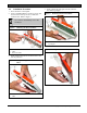
D1255RB/D1256RB/D1257RB | Installation Instructions | 3.0 3.3 1. 2. Installation Procedure Power down the control panel. Using a small flat-bladed screwdriver, gently push the two bottom tabs up and in to release the enclosure base. Refer to Figure 2. 4. Installation Gently pull the keypad apart from the enclosure base at the top hinges. Figure 4: Removing the Enclosure Base Use caution to avoid damage to the tabs and hinges.
D1255RB/D1256RB/D1257RB | Installation Instructions | 3.0 Installation . Figure 6: Removing the Red Cover 7. Set the address switches. Refer to Figure 8, Figure 9,, and Table 1. Figure 8: Setting the Address Switches 1 - Red cover Remove the faceplate.
D1255RB/D1256RB/D1257RB | Installation Instructions | 3.0 Figure 11: Wiring Harness Connection to Keypad or Annunciator Warning: Avoid injury. Do not wire the D1255RB, D1256RB, or D1257RB if power is applied to the control panel. 8. Installation Connect the flying leads on the wiring harness (Figure 10) to the wiring terminals on the control panel. Refer to Table 2.
D1255RB/D1256RB/D1257RB | Installation Instructions | 4.0 D1256RB Programming Requirements . 4.1 4.0 D1256RB Programming Requirements • For D1255RB and D1257RB programming information, refer to the appropriate program entry guide and program record sheet for the control panel. Important programming recommendations and requirements are described in this section.
D1255RB/D1256RB/D1257RB | Installation Instructions | 4.0 4.
D1255RB/D1256RB/D1257RB | Installation Instructions | 4.0 D1256RB Programming Requirements . 4.4.1 Menu Item and Function Table 3: Program the first ten menu items as indicated in Table 3. This programming is necessary for the D1256RB to operate properly. The first four keys on the D1256RB execute the first four menu items enabled at the keypad address. Menu items five through ten are optional features that can be programmed into the D1256RB system.
D1255RB/D1256RB/D1257RB | Installation Instructions | 4.0 4.4.5 Keypad (Command Center) Functions The following keypad function must be enabled or passcode required to enable the [DETECTOR RESET] key. • #27 Reset Sensors Include the following items in the menu: • #9 View Event Memory • #10 View Point Status • #12 Fire Test • #21 View Log • #29 Remote Program • #32 Display Rev Refer to Figure 18.
D1255RB/D1256RB/D1257RB | Installation Instructions | 5.0 Specifications . Ensure that CF 128 through CF 131, and any other functions you are using in the menu, are programmed E (enabled), not P (passcode required). Refer to Figure 19.
Bosch Security Systems, Inc. 130 Perinton Parkway Fairport, NY 14450-9199 Customer Service: (800) 289-0096 Technical Support: (888) 886-6189 © 2006 Bosch Security Systems, Inc.