
Specifications

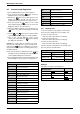

6 720 646 812
Maintenance and service
43
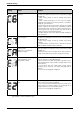
B Remove the condensing heat exchanger unit from
the appliance by pulling it towards you.
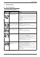
B Dismantle all parts for inspection and cleaning.
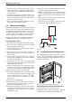
Fig. 67 Condensing heat exchanger
B Check the condensing heat exchanger for any
obstruction.
B Flush the condensing heat exchanger unit with water.
B Check all gasket and o-rings for damage and replace
if necessary.
B Assemble the condensate unit and all other parts in
reverse order of disassembly.
6.5 Adjusting CO
2
The CO
2
can only be adjusted by a certified gas
technician with a calibrated CO
2
analyzer.
Static Gas Pressure: “ WC
P1 Operating Pressure: “ WC
The P1 minimum operating gas pressure is 3.5" WC for
Natural Gas and 8" WC for Propane. Do not proceed in
adjusting CO
2
until pressure is at or above these levels,
but not to exceed 10.5" WC for Natural Gas and 13"
WC for Propane.
A. Once Gas Pressure is adequate
B Press ON/OFF button to turn OFF the heater.
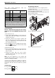
B Remove brass flat head screw on the exhaust collar
as seen in Fig. 68.
B Insert CO
2
analyzer probe into the measuring port.
The tip of the probe should be in the center of the flue
pipe (approx 1.5" inserted). Avoid air gaps between
probe and measuring port as they can alter readings.
Fig. 68 Measuring port
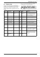
B While holding the Program (P) button, press the ON/
OFF button to turn ON the heater (see Fig. 69). As
soon as ‘188’ flashes on the display, release the
Program button. The display should now read P2.
Press button until “P1” appears on display.
Fig. 69
B. Measuring CO
2
(Combustion cover Installed):
B Open all hot water taps to achieve a flow rate of at
least 6 gallons per minute. (1 tub and 2 sinks should
be sufficient). If heater display reverts back to P2,
open more hot water fixtures to allow sufficient flow.
Press + until P1 reappears on the display.
B Record the CO
2
reading in P1 below. (Analyzer
reading may take several minutes to stabilize).
B Press the ‘+’ button until P2 appears. Unit will ramp
down to low fire and the water flow should decrease.
B Record the CO
2
reading in P2 below.
P1 CO
2
Reading: % CO
2
P2 CO
2
Reading: % CO
2
i
It is important to inspect and propely
replace the gaskets and o-rings.
i
CO
2
adjustment is required in Natural
Gas installations where energy content
is less than 900 BTU/cuft, and in
installations with repeated unresolved
EA and EC errors (ref. to page 49
“Problem solving”).
Caution: One factor that may affect
CO
2
levels is improper gas pressure.
Please see Chapter 3.14 for the
procedure to measure gas pressure
and record your findings below: