Command Center D1260 Installation Guide
D1260 D1260 Installation Guide 48101D Page 2 © 2003 Bosch Security Systems
D1260 Contents 1.0 1.1 1.2 1.3 1.3.1 1.3.2 2.0 2.1 2.2 2.2.1 2.2.2 2.2.3 2.2.3.1 2.2.4 2.3 3.0 3.1 3.1.1 3.1.2 3.2 3.3 3.4 3.5 4.0 4.1 4.2 4.3 4.4 4.5 4.6 Introduction........................................................................................................................................................................................... 5 Manual Organization ......................................................................................................................................
D1260 Contents Tables Table 1: D1260 Installation Guide Manual Organization.......................................................................................................... 5 Table 2: Other Literature Referenced............................................................................................................................................ 5 Table 3: Upgrade Kits ...............................................................................................................................
D1260 Introduction 1.0 Introduction 1.1 Manual Organization This manual is divided into 4 sections. A summary of each section is detailed in the table below. Section 1 2 3 4 Description Introduction Overview Installation Programming the Panel Table 1: D1260 Installation Guide Manual Organization 1.2 Other Literature Referenced Throughout this manual, references will be made to other documentation.
D1260 Introduction 1.3.2 Tips, Important Notes, Cautions and Warnings Throughout this document, helpful tips, important notes, cautions and warnings will be presented for the reader to keep in mind. These appear different from the rest of the text as follows: Important Notes - should be heeded for successful operation and programming. Also tips and shortcuts may be included here. Caution - These caution the operator that physical damage to the program and/or equipment may occur.
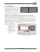
D1260 Overview 2.0 D1260 Overview The D1260 Command Center is a SDI Bus compatible device used with the D9412G, D7412G, D7212G, D9412, D7412, D7212, and D9112 Control/Communicators with versions 6.40 or higher. If you need to upgrade your control panel, you may order the following upgrade kit at no charge (see Table 3).
D1260 Overview 2.1 Specifications Power Requirements Enclosure Temperature Display Voltage Nominal Standby Current Idle 95 mA 200 mA Maximum (with speaker volume and display backlight at maximum) 4.6 in. x 8.2 in. 0.8 in. (11.7 cm x 21 cm x 2 cm) 15.5 oz. (439 g) Off White GE Cycoloy CH10 UL94-HB Fire Rated Intended for indoor use +32°F to +120°F (0°C to +49°C) +90°F +3°F (32°C +2°C) Backlit LCD 3.4 in. x 1.4 in. (86.4 mm x 35.
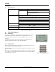
D1260 Overview 2.2.3 Command Center Function Keys The D1260 has ten numeric keys, two dedicated keys (see Table 5) and 8 soft keys (see Section 2.2.3.1 Soft Keys), that are used to control your system. Key Command Picture ENTER Description Use the [COMMAND] key in combination with one or two numeric keys to perform a function. Use the [ENTER] key to complete the entry of your passcode at the command center. Table 5: D1260 Command Center Function Keys 2.2.3.
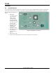
D1260 Overview 2.3 Internal Features To access the inside of the D1260, the back cover must be removed. Using a small flat-blade screwdriver, gently push in the two holes in the bottom of the D1260. As the tabs are pushed in, lift the back plate away from the rest of the unit. The following internal features are found: 1. DIP Switch (6-position) - allows you to select the address of each command center, and enable/ disable the keypad encoding tone. (See Section 3.2 Setting the DIP Switch on page 12) 2.
D1260 Installation 3.0 Installation 3.1 Mounting The D1260 Command Center is a low profile, surface-mounted unit. It can also be mounted using the following optional packages: 3.1.1 3.1.
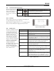
D1260 Installation 3.2 Setting the DIP Switch To access the DIP switch, the back cover must be removed. Using a small flatblade screwdriver, gently push in the two holes in the bottom of the D1260. As the tabs are pushed in, lift the back plate away from the rest of the unit. ON Switches 1 through 3 assign the address for the specific command center. 1 2 3 4 5 6 Figure 7: D1260 DIP Switch Note: Each D1260 Command Center must be assigned to a unique address.
D1260 Installation 3.5 Wiring A 4-wire flying lead is required for the data and power connections between the D1260 and the panel. The D1260 comes with a wiring assembly consisting of four color-coded flying leads and a female 4-pin connector plug at one end. Wire resistance must not exceed 14 Ω. It is recommended that 18 AWG wire be used when connecting a D1260 to a control panel. To wire the D1260: 1. Power down the panel. 2.
D1260 Installation Notes: D1260 Installation Guide 48101D Page 14 © 2003 Bosch Security Systems
D1260 Programming the Panel 4.0 Programming the Panel The D1260 Command Center is compatible with the D9412G, D7412G, D7212G, D9412, D7412, D7212, and D9112 Control/Communicators with versions 6.40 or higher. To program the D1260, version 1.15 or higher of the 9000MAIN handler or version 3.60 or higher of RAM IV is required. 4.1 Enabling the D1260 Command Center In RAM IV, it is located in the COMMAND CENTER (9000MAIN) section and called Enhanced Command Center.
D1260 Programming the Panel 4.2 Programming Area Names When the D1260 is installed with D9412G, D7412G, D9412, D7412, D7212, and D9112 Control/Communicators, Points 240 to 247 are used for the Area Text Name for the Area (1 to 8) that the D1260 is assigned to. When the D1260 is installed with the D7212G Control/Communicator, Points 240 to 243 can be used for Area Text Name for the Area (1 to 4) that the D1260 is assigned to.
D1260 Programming the Panel 4.5 Programming Custom Functions When programming Custom Functions for use on a D1260 Command Center, program the keystrokes as if you were using a D1255 Command Center. Please refer to the panel’s Program Entry Guide and Program Record Sheet for full details on how to program Custom Functions. 4.
D1260 Programming the Panel Notes: D1260 Installation Guide 48101D Page 18 © 2003 Bosch Security Systems
D1260 Programming the Panel Notes: D1260 Installation Guide © 2003 Bosch Security Systems Page 19 48101D
© 2003 Bosch Security Systems 130 Perinton Parkway, Fairport, NY 14450-9199 USA Customer Service: (800) 538-5807; Technical Support: (888) 886-6189 48101D Installation Guide 05/03 D1260 Page 20 of 20