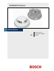
D263/D273 Series Installation Instructions EN Photoelectric Smoke Detector
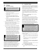
D263/D273 Series | Installation Instructions | 1.0 Overview Notice Install, test, and maintain the D263/D273 Series according to these instructions, NFPA 72, Local Codes and the authority having jurisdiction (AHJ). Failure to follow these instructions can result in the detectors not operating properly. Bosch is not responsible for improperly installed, tested, or maintained devices. The LED on the D273IS latches on during an alarm from heat but not from smoke.
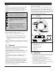
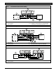
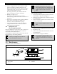
D263/D273 Series | Installation Instructions | 3.0 Wiring . Figure 2: Mounting a D263/D273 Series Detector Refer to your control panel’s installation instructions for EOL resistor selection. Figure 3: D263 Series/D263TH Wiring – IN – + OUT IN 1 1 2 – IN 4 1 3 – + + OUT IN OUT 2 3 4 – + 1 3 2 + OUT 2 1 - Alarm loop 2 - EOL resistor 1 - Wire entrance 2 - Locking tab 3 - Mounting holes Figure 4: D273ES/D273THES Wiring 1 3.
D263/D273 Series | Installation Instructions | Figure 6: 3.
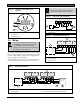
D263/D273 Series | Installation Instructions | 4.0 Testing . 4.3 4.0 Testing 4.1 Operational Testing Before and after maintaining or testing the fire alarm system, notify all concerned parties. 1. Apply power to the system and check for alarms. a. Note which detectors are in alarm (if any) and remove power to the system. b. Remove the alarmed detectors and recheck for proper wiring. c. If the problems persist, replace the affected detectors or swap them with known good units.
D263/D273 Series | Installation Instructions | 2. 5.0 Maintenance Connect a digital voltmeter to the D1005 Test Cable. Pay particular attention to the screens when cleaning the detector. In dusty areas or areas of heavy insect concentration, you might need to clean the screens more often. Connect the negative terminal of the meter to the black wire of the D1005, and then connect the positive terminal of the meter to the test cable’s red wire. The white wire of the D1005 is not used. 3.
D263/D273 Series | Installation Instructions | 6.0 Specifications . 6.0 Specifications Table 1: Specifications Wiring Standby Voltage Maximum RMS Ripple Current Power up Relay Contacts Operating Temperature Dimensions (H x D) Control Panel Compatibility Patents D263 Series Two-wire 8.5 VDC to 33 VDC D273 Series Four-wire 10 VDC to 30 VDC 25% of DC input Refer to Table 2. 22 sec maximum Form A: 0.5 A; 200 VDC Form C: 120 VAC/30 VDC at 1 A, 30 W maximum +32°F to +100°F (0°C to +38°C); 0 to 95% RH 2 in.
Bosch Security Systems, Inc.