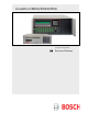
Conettix D6600/D6100IPv6 Program Entry Guide EN Receiver/Gateway
Conettix D6600/D6100IPv6 | Program Entry Guide | Trademarks Trademarks Trademark names are used throughout this document. In most cases, these designations are claimed as trademarks or registered trademarks in one or more countries by their respective owners. Rather than placing a trademark symbol in every occurrence of a trademark name, Bosch Security Systems, Inc.
Conettix D6600/D6100IPv6 | Program Entry Guide | UL 864 Required Settings . UL 864 Required Settings Notice to users, installers, authorities having jurisdiction (AHJ), and other involved parties: This product incorporates field-programmable software.
Conettix D6600/D6100IPv6 | Program Entry Guide | Contents Contents 1.0 1.1 1.2 2.0 2.1 2.1.1 2.1.2 2.1.3 2.1.4 2.1.5 2.1.6 2.1.7 2.1.8 2.1.9 2.1.10 2.2 2.2.1 2.2.2 2.2.3 2.2.4 2.2.5 2.2.6 2.2.7 2.2.8 2.2.9 2.2.10 2.2.11 2.2.12 2.2.13 2.2.14 2.2.15 2.2.16 2.2.17 2.2.18 2.2.19 2.2.20 2.2.21 2.2.22 2.2.23 2.2.24 2.2.25 2.2.26 2.2.27 2.2.28 2.2.29 2.2.30 2.2.31 2.2.32 4 Event Database .................................... 7 Display Sort by Time/Date ....................... 7 Display Current System Troubles ...
Conettix D6600/D6100IPv6 | Program Entry Guide | Contents . 2.5.9 2.5.10 2.5.11 2.5.12 2.5.13 2.5.14 2.5.15 2.5.16 2.5.17 2.6 3.0 3.1 3.1.1 3.1.2 3.1.3 3.1.4 3.1.5 3.1.6 3.1.7 3.1.8 3.1.9 3.2 3.2.1 3.3 3.3.1 4.0 4.1 4.2 4.3 4.4 4.5 4.5.1 4.5.2 4.5.3 4.5.4 4.5.5 4.5.6 4.5.7 4.5.8 4.5.9 5.0 5.1 6.0 6.1 6.1.1 6.1.2 6.1.3 Trailer .................................................... 17 BFSK Fire Bit ......................................... 17 Modem IIe Fire .......................................
Conettix D6600/D6100IPv6 | Program Entry Guide | Contents 6.7.8 6.7.9 6.7.10 6.7.11 6.7.12 6.7.13 6.7.14 6.7.15 6.7.16 6.8 6.8.1 6.8.2 6.8.3 6.8.4 6.8.5 Event 4-2 – Digit 7 ................................. 45 Event 4-2 – Digit 8 ................................. 45 Event 4-2 – Digit 9 ................................. 45 Event 4-2 – Digit A ................................. 45 Event 4-2 – Digit B ................................. 45 Event 4-2 – Digit C .................................
Conettix D6600/D6100IPv6 | Program Entry Guide | 1.0 Event Database . 1.0 Event Database The Event Database stores all trouble conditions and alarm messages that occur in the D6600/D6100IPv6. The maximum number of events stored in the database is 20,000 for the D6600 and 2000 for the D6100IPv6. After the database reaches capacity, the next event forces the oldest event out of the database. This is typically known as First In, First Out (FIFO).
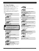
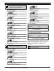
Conettix D6600/D6100IPv6 | Program Entry Guide | 2.0 2.0 CPU Configuration 2.1 Change Password A password can be up to eight hexadecimal (0 to 9 and A to F) characters. For security purposes, change all default passwords. 2.1.1 Manager Password Default (D6600): (D6100IPv6): 6600 6100 The manager has full access to all programming options. The D6600/D6100IPv6 LCD shows: To change the password: 1. 2. 3. 4. 5. 6. 7.
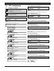
Conettix D6600/D6100IPv6 | Program Entry Guide | 2.0 CPU Configuration . The Time and Date display format is determined by the programming for Menu Item 2.2.3 Set Country. 4. 5. 1. 2. 3. D6 6 00 D6100IPv6 M/E ENTER D6600 D6100IPv6 M/E ENTER 6. 2.2.3 4. D6600 D6100IPv6 M/E ENTER Enter the current time. 5. 6. D6600 D6100IPv6 M/E ENTER D6 6 0 0 D 6 1 00 IPv6 C A N CANCEL 2.2.2 Date Setup 2. 3.
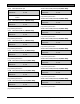
Conettix D6600/D6100IPv6 | Program Entry Guide | 2.0 2.2.5 Line Card 1 Line 1, 2 CPU Configuration 2.2.13 Line Card 5, Line 17, 18 (D6600 Only) Default: 1 Default: 0 Selections: 0 or 1 Selections: 0 or 1 0 Disable 1 Enable 2.2.6 Refer to Menu Item 2.2.5 Line Card 1 Line 1, 2 for programming information. 2.2.14 Line Card 5, Line 19, 20 (D6600 Only) Line Card 1, Line 3. 4 (D6600 Only) Default: 0 Selections: 0 or 1 Refer to Menu Item 2.2.
Conettix D6600/D6100IPv6 | Program Entry Guide | 2.0 . 2.2.21 Buzzer 2.2.25 Point/User Text Default: 3 Default: 1 Selections: 0 to 4 Selections: 0 to 2 0 Buzzer off 1 Buzzer on for any events 2 Buzzer on for system trouble conditions 3 Buzzer on for new events when the automation link fails or any system trouble conditions occur 4 CPU Configuration Buzzer on for new events when printer link fails or any system trouble conditions occur 2.2.
Conettix D6600/D6100IPv6 | Program Entry Guide | 2.0 Refer to Input and Output Ports in the D6600/D6100IPv6 Operation and Installation Guide (P/N: 4998122704). 2.2.29 CPU Programmable Input 2 Default: 0 Selections: 0 to 2 0 The UPS AC Lost or the Low Battery signal is not monitored. 1 Monitoring the UPS AC Lost. 2 Monitoring the UPS Low Battery. The D6600/D6100IPv6 is connected to an uninterruptible power supply (UPS), and monitors the AC Lost signal and the Low Battery signal supplied by the UPS.
Conettix D6600/D6100IPv6 | Program Entry Guide | 2.0 . 2.2.34 Battery Supervision Default: 1 Selections: 0 or 1 0 Battery is not supervised. 1 Battery is supervised. When Battery Supervision is 1, and the battery is disconnected or low, a BATTERY MISSING or BATTERY BAD message appears on the display, and the green power LED flashes. The trouble message also prints or is sent to the computer automation system when those options are enabled.
Conettix D6600/D6100IPv6 | Program Entry Guide | 2.0 2.3 Line Group This section contains program items that determine how lines are supervised and how incoming messages are identified by the D6600. ULC requires the following: If the lines (numbers) are in a single hunt group (refer to the definition in CAN/ULC-S304-06), they shall be individually accessible; otherwise, separate hunt groups shall be required.
Conettix D6600/D6100IPv6 | Program Entry Guide | 2.0 . 2.3.7 Line Card 2/Line 3 (L07) (D6600 Only) 2.3.16 Line Card 4/Line 4 (L16) (D6600 Only) Default: 00 Default: 00 Selections: 00 to 99 Selections: 00 to 99 Refer to Menu Item 2.3.1 Line Card 1/Line 1 (L01) for programming information. 2.3.8 Line Card 2/Line 4 (L08) (D6600 Only) Refer to Menu Item 2.3.1 Line Card 1/Line 1 (L01) on page 14 for programming information. 2.3.
Conettix D6600/D6100IPv6 | Program Entry Guide | 2.0 2.3.25 Line Card 7/Line 1 (L25) (D6600 Only) Default: 00 Selections: 00 to 99 Refer to Menu Item 2.3.1 Line Card 1/Line 1 (L01) on page 14 for programming information. 2.3.26 Line Card 7/Line 2 (L26) (D6600 Only) Default: 00 Selections: 00 to 99 CPU Configuration 2.
Conettix D6600/D6100IPv6 | Program Entry Guide | 2.0 . 2.4.4 2.4.10 BFSK Fire Bit Parity Default: 0 Default: 0 Selections: 0 to 2 Selections: 0 or 1 0 None 1 Even 2 Odd CPU Configuration 0 Fire messages are sent to the automation PC as standard alarms, troubles, and restorals. 1 Fire messages are sent to the automation PC with the digit character codes as shown in Table 3 (refer also to the D6600/D6100IPv6 Computer Interface Manual [P/N: 4998122703] for the digit character codes).
Conettix D6600/D6100IPv6 | Program Entry Guide | 2.0 CPU Configuration 2 BFSK and Modem IIe /Modem IIIa Fire Bit Examples Some control panels offer enhanced fire messages in 2 BFSK, and Modem IIe and Modem IIIa formats. This entry determines how the D6600/D6100IPv6 presents 2 BFSK, or Modem IIe and Modem IIIa fire messages to the automation PC (see Table 3 ). This entry has no affect on how the messages print. 2.4.
Conettix D6600/D6100IPv6 | Program Entry Guide | 2.0 CPU Configuration . 2.4.12 SIA Fire Restore 2.4.14 Sub Subscriber Default: 0 Default: 0 Selections: 0 or 1 Selections: 0 or 1 0 The automation PC sends a common Fire Restoral code if programmed for SIA Output Mode. 1 The automation PC differentiates between Fire Restoral after Alarm and Fire Restoral after Trouble, Missing, or Supervisory if programmed for SIA Output Mode.
Conettix D6600/D6100IPv6 | Program Entry Guide | 2.0 CPU Configuration 2.4.16 SFSK1 Output Default: 0 Selections: 0 to 1 0 Send the SFSK 1 (Table 7 on page 21) messages to the automation software (Table 5). 1 Send the SFSK 1 sensor to the automation software (Table 6). At SFSK 1 format, change the automation output to either message (Table 5) or sensor (Table 6). Table 5: SFSK 1 Message Example Mode 6500 SIA Example hmrrlsAAAAAAAA"EEZZ"EEZZ"EEZZ....
Conettix D6600/D6100IPv6 | Program Entry Guide | 2.0 CPU Configuration .
Conettix D6600/D6100IPv6 | Program Entry Guide | 2.0 CPU Configuration 2.4.17 Format ID (D6600 Only) Default: 0 Selections: 0 or 1 0 Traditional Message Type for output format. 1 Unique Message Type for each format. Table 8: D6500 Automation Mode Output Format Message Type Format(s) 2.5.
Conettix D6600/D6100IPv6 | Program Entry Guide | 2.0 CPU Configuration .
Conettix D6600/D6100IPv6 | Program Entry Guide | 3.0 2.5 Return CPU Configuration to Default Line Card Configuration 3.0 Line Card Configuration 3.1 1. 2. 3. D6600 D6100IPv6 M/E ENTER D6600 D6100IPv6 D6600 D6100IPv6 M /E 4. D 66 0 0 MENU D 61 0 0IPv6 5x 5. Default: 2 Selections: 1 to 21 0 No handshake, not accepted for Tone 1 1 1400 Hz 2 2300 Hz 3 Modem II 4 Modem IIe/IIIa (D6640 v.01.XX.
Conettix D6600/D6100IPv6 | Program Entry Guide | 3.0 Line Card Configuration . Program the ITI handshake before the Modem II handshake when receiving ITI format signals. Program the SIA handshake before the Modem II handshake when receiving SIA format signals. If using Handshake 18 or 20, program it as the first tone with no other handshakes programmed for that line. 3.1.1.2 Tone 2 Default: 1 Selections: 0 to 21 Refer to Menu Item 3.1.1.1 Tone 1 on page 24 for programming information. 3.1.1.
Conettix D6600/D6100IPv6 | Program Entry Guide | 3.0 3.1.2 Phone Supervision 3.1.2.1 Line Sniff Line Card Configuration 3.1.3 Line Formats 3.1.3.1 Five Digits Default: 1 Default: 4 Selections: 0 to 2 Selections: 1 to 4 0 Disable phone line supervision. 1 Enable phone line supervision. 2 Disable phone line supervision and disable Busy Seconds Report. This entry enables or disables phone line supervision.
Conettix D6600/D6100IPv6 | Program Entry Guide | 3.0 Line Card Configuration . 3.1.3.3 4-1 Extended Default: 1 Selections: 0 to 2 0 No combination of 4-1 format and 4-1 extended format. Example: Control panel sends to receiver 12341 11112 Automation format message sent to central station: 1 2 This selection uses the fifth position of the first signal and fifth position of the second extended signal (when both are 1 to 9) and combines them into a two-digit zone number.
Conettix D6600/D6100IPv6 | Program Entry Guide | 3.0 3.1.3.4 4-2 Extended Line Card Configuration 3.1.3.8 Digit Wait (× 100 ms) Default: 1 Default: 17 Selections: 0 or 1 Selections: 04 to 20 0 The 4-2 Extended messages are not combined. 1 Combine the two signals of the 4-2 Extended format to create 4-3 format output. 3.1.3.5 Seven digit Default: 2 Selections: 1 to 3 1 The seven-digit pulse format at 40-baud is decoded as SESCOA Super Speed format.
Conettix D6600/D6100IPv6 | Program Entry Guide | 3.0 Line Card Configuration . 3.1.3.12 3-1 Extended Default: 1 Selections: 0 to 2 0 No combination of 3-2 format and 3-1 extended format. Example: Control panel sends to receiver: 1231 1112 Automation format message sent to central station: 1 2 This selection uses the fourth position of the first signal and fourth position of the second extended signal (when both are 1 to A) and combines them into a two-digit zone number.
Conettix D6600/D6100IPv6 | Program Entry Guide | 3.0 Line Card Configuration 3.1.3.13 3-1 Restore Report in High Speed Format Default: 0 Selections: 0 or 1 0 Normal 3-1 report 1 Convert a 3-1 Restore Report to an Ademco High Speed report. Example: Account 123, and Zone 2 Restore are translated to: * 0123 5355 5555 7 Messages: AAA Z AAA 9, where: where AAA = Account Code Z = Zone 9 = Restore * A leading 0 is added in front of the account code. 3.1.3.
Conettix D6600/D6100IPv6 | Program Entry Guide | 3.0 . 3.1.3.16 Ademco CAPS 4-2 None O/C Report Line Card Configuration 3.1.3.20 GSM/VoIP Compensation Default: 0 Default: 0 Selections: 0 or 1 Selections: 0 or 1 0 Send the unconverted 4-2 messages to the automation software. 1 Send the CAPS 4-2 Report to the automation software.
Conettix D6600/D6100IPv6 | Program Entry Guide | 3.0 There are three two-way audio modes of operation: • Transfer: The D6600/D6100IPv6 transfers the incoming line to another line. At the end of the alarm signal, the receiver quickly disconnects and reconnects the line, then dials another line which is programmed in Menu Item 3.1.4.19 Transfer Phone Number on page 33. Entries in Menu Item 3.1.4.18 Flash (x 100ms) on page 33 and Menu Item 3.1.4.19 Transfer Phone Number are necessary for this to happen.
Conettix D6600/D6100IPv6 | Program Entry Guide | 3.0 . 3.1.4.14 Account Digit C Line Card Configuration 3.1.4.20 Hold Default: 0 Default: 00 Selections: 0 or 1 Selections: 00 to 99 Refer to Menu Item 3.1.4.3 Account Digit 1 for programming options. 3.1.4.15 Account Digit D Default: 0 Selections: 0 or 1 Refer to Menu Item 3.1.4.3 Account Digit 1 for programming options. 3.1.4.16 Account Digit E Default: 0 Selections: 0 or 1 Refer to Menu Item 3.1.4.
Conettix D6600/D6100IPv6 | Program Entry Guide | 3.0 A signal must possess all three attributes (account number, event code, and zone code) to trigger a TWA session. For example: • 4-2 Alarm 123456 activates a TWA session • 4-2 Alarm 123466 does not activate a TWA session 3.1.5 Line Identification 3.1.5.1 Caller ID Default: 0 Selections: 0 to 3 0 Disable Caller ID. 1 Output Caller ID to Automation and Printer. 2 Output Caller ID to Printer only.
Conettix D6600/D6100IPv6 | Program Entry Guide | 3.0 . 3.1.7 Event 3-1 or 4-1 This section can only be programmed using the D6200 Programming Software. Table 12 shows the programmed event codes and corresponding descriptions (in English). Table 12: Event 3-1 or 4-1 (Line Configuration) Event Codes Event Code A R O C T \ Other Description ALARM RESTORE OPEN CLOSE TROUBLE CANCEL ALARM 3.1.7.1 Event 3-1 – Digit 0 Default: A Selections: 0 to 9, A to Z, or \ Refer to Menu Item Event 3-1 or 4-1. 3.1.7.
Conettix D6600/D6100IPv6 | Program Entry Guide | 3.0 3.1.8.1 Event 4-2 – Digit 0 Line Card Configuration 3.1.8.11 Event 4-2 – Digit A Default: A Default: A Selections: 0 to 9, A to Z, or \ Selections: 0 to 9, A to Z, or \ Refer to Menu Item Event 3-1 or 4-1 on page 34. 3.1.8.2 Event 4-2 – Digit 1 Refer to Menu Item Event 3-1 or 4-1 on page 34. 3.1.8.
Conettix D6600/D6100IPv6 | Program Entry Guide | 3.0 . 3.1.9.2 Receiver Type (D6600 Only) Default: 0 Selections: 0 to 9 0 1 2 3 4 5 6 7 8 9 Line Card Configuration D6600 M/E Bosch Security Systems, Inc. ADEMCO 685 FBI CP220 Osborn-Hoffman Quick Alert I/II Silent Knight 9000 Varitech Sur-Gard MLR2-DG ITI CS4000 DMP C&K Enter the receiver type. D6600 M/E D6600 CAN The selections made determine the database the automation software uses to manage the incoming signals from this specific line.
Conettix D6600/D6100IPv6 | Program Entry Guide | 3.0 3.1.9.3 Acron 3-8 Account Output (D6600 Only) Default: 0 Selections: 0 or 1 0 The D6600 sends a three-digit account code to the automation software. 1 The D6600 sends a leading space to the automation software. ACRON 3-8 format has a three-digit account code. Setting this option to 0 allows the D6600 to send a three-digit account code to the automation software in AAA form.
Conettix D6600/D6100IPv6 | Program Entry Guide | 4.0 Host Programming . 3.3 Copy Selected Line Configuration to Another Line 3.3.1 Copy Selected Line Configuration from the Keypad Use this option to copy the settings from one line to another. 1. D6 6 00 D 6 10 0IPv6 2x 2. 3. D6600 D6100IPv6i M/E ENTER D 66 0 0 D 61 0 0IPv6 4.0 Host Programming 4.1 4.2 4.3 4.4 4.
Conettix D6600/D6100IPv6 | Program Entry Guide | 5.0 4.5.8 4.5.9 Remote Access Permission (Reserved Feature) RS-232 Direct Access Permission Default: 1 Selections: 0 or 1 0 Disable D6200 connection. 1 Enable D6200 connection. Firmware Version 5.0 Firmware Version 5.1 1. Checking CPU and Line Card Firmware Versions D6 6 00 D 6 100 IPv6 4x 2. 3. D6600 D6100IPv6 M/E ENTER D6 6 00 D 6 10 0IPv6 Scroll down through the installed line cards (D6600 can have up to eight).
Conettix D6600/D6100IPv6 | Program Entry Guide | 6.0 Network Configuration . 6.0 Network Configuration 6.1 0 For all references to the D6686, refer to the provided Installation Supplement for the specific model number of the Network Ethernet Module. Selections: 0 to 2 0 Disable COM4 Network Adapter connection (RS-232 to D6200).
Conettix D6600/D6100IPv6 | Program Entry Guide | 6.0 6.2.4 COM1 Stop Bit Network Configuration 6.3.1 IP Address Default: 1 Selections: Selections: 1 or 2 [IPv4] xxx.xxx.xxx.xxx Select the stop bit value for COM1. 6.2.5 Network Adapter Default: 0 Selections: D6600: 0 to 3 D6100IPv6: 0 or 2 0 Disable network adapter connection. 1 Enable network adapter connection for D6600 with D6680 or D6100IPv6. 2 Enable network adapter connection for D6600 with D6682 or D6100IPv6.
Conettix D6600/D6100IPv6 | Program Entry Guide | 6.0 . 6.3.6 Network Automation Output Format 6.4.2 IP Address 2 Default: 0 Selections: Selections: 0 to 2 [IPv4] xxx.xxx.xxx.xxx 0 Disable network automation output. 1 D6500 Mode automation output. 2 Bosch SIA Mode automation output. If after selecting an automation output, you decide to disable automation (select 0), reboot the receiver for proper operations. Selection 0 completely disables automation output when Menu Item 6.3.
Conettix D6600/D6100IPv6 | Program Entry Guide | 6.0 If a password is entered here, the D6200 can connect to the receiver from any PC and location as long as the D6200 PC has this password entered in it. If this field is (blank), this function will be disabled in the receiver and D6200 workstations can only connect if the static IP Address of the workstation is in the receiver. Password is case sensitive. 6.5 Network Printer (Reserved) Section 6.5 is reserved. 6.
Conettix D6600/D6100IPv6 | Program Entry Guide | 6.0 . 6.6.15 Event 3-1 – Digit E 6.7.9 Network Configuration Event 4-2 – Digit 8 Default: R Default: A Selections: 0 to 9, A to Z, or \ Selections: 0 to 9, A to Z, or \ Refer to Table 13 for details. 6.6.16 Event 3-1 – Digit F Refer to Table 13 on page 44 for details. 6.7.10 Event 4-2 – Digit 9 Default: T Default: A Selections: 0 to 9, A to Z, or \ Selections: 0 to 9, A to Z, or \ Refer to Table 13 on page 44 for details. 6.
Conettix D6600/D6100IPv6 | Program Entry Guide | 6.0 6.8.2 Substitution Monitor Default: 3 Selections: 0 to 9 0 Use to disable the Substitution monitor and Menu Item 6.8.3 Disable Account by Substitution. 1 to 9 Number of consecutive error packages sent before a Substitution Alarm event is generated. Programming the substitution monitor allows the D6600/D6100IPv6 to identify whether an alarm is real or a trick by someone sending a recording of a valid control panel signal. 6.8.
Conettix D6600/D6100IPv6 | Program Entry Guide | 7.0 Database Configuration . 7.0 Database Configuration 8.0 Registered Accounts Bosch recommends using the D6200 for adding, deleting, or modifying the account database. Shows the maximum number of accounts and the current number of accounts in the D6600/D6100IPv6. 7.1 Add or modify an account [ENTER] Input NNC Account: ______ [1][2][3][4][5][6] [ENTER] 7.1.
Conettix D6600/D6100IPv6 | Program Entry Guide | Contents Appendix A: Important Information Table 14: Important Information Receiver Number: Line Phone Numbers and Other Notes: Slot 1/Line 1 (L01) Slot 1/Line 2 (L02) Slot 1/Line 3 (L03) Slot 1/Line 4 (L04) Slot 2/Line 1 (L05) Slot 2/Line 2 (L06) Slot 2/Line 3 (L07) Slot 2/Line 4 (L08) Slot 3/Line 1 (L09) Slot 3/Line 2 (L10) Slot 3/Line 3 (L11) Slot 3/Line 4 (L12) Slot 4/Line 1 (L13) Slot 4/Line 2 (L14) Slot 4/Line 3 (L15) Slot 4/Line 4 (L16) ____________
Bosch Security Systems, Inc. 130 Perinton Parkway Fairport, NY, 14450 USA www.boschsecurity.com © Bosch Security Systems, Inc.