D7212GV2 Program Entry Guide EN Control Panel
D7212GV2 | Program Entry Guide | 1.0 Introduction EN | 2 Documentation Conventions Type Styles Used in this Manual To help identify important items in the text, the following type styles are used: Prompt A thick border is used to indicate a main programming entry as seen in the Remote Programmer’s Display. It is used as a section heading and screen example. Shaded boxes indicate programmer prompts that are only available when Custom or View events are selected.
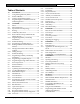
D7212GV2 | Program Entry Guide | Table of Contents Table of Contents 1.0 1.1 1.2 1.3 1.4 2.0 2.1 2.2 2.2.1 2.3 2.3.1 2.3.2 2.3.3 2.3.4 2.3.5 2.3.6 2.3.7 2.3.8 2.4 2.4.1 2.4.2 2.4.3 2.5 2.6 2.7 2.7.1 2.7.2 2.7.3 2.8 2.9 2.9.1 2.9.2 2.9.3 2.9.4 2.9.5 2.9.6 2.10 2.10.1 2.10.2 Introduction.......................................................5 Using this Program Entry Guide ......................5 Product Handlers................................................6 Guide to Programming Options .................
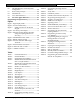
D7212GV2 | Program Entry Guide | Table of Contents EN | 4 6.6 Table 20: Figures Table 21: Table 22: Table 23: Table 24: Table 25: Table 26: Table 27: Table 28: Table 29: Table 30: Table 31: SDI RPS/Enhanced Communications Configuration ..................................................128 6.7 Route Group Attempts...................................129 6.8 Miscellaneous..................................................129 6.9 Cross Point Parameters ..................................132 7.
D7212GV2 | Program Entry Guide | 1.0 Introduction 1.0 Introduction 1.1 Using this Program Entry Guide This guide is only for programming the D7212GV2 Control Panel.
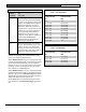
D7212GV2 | Program Entry Guide | 1.0 1.2 Introduction EN | 6 Product Handlers Programming the D7212GV2 requires multiple product handlers. The availability of each handler is indicated in Table 2. Refer to the release notes to determine the most current handler versions. Table 2: Product Handlers Product Handler GV2MAIN Compatible Versions V1.03 and above RADXUSR1 V1.06 and above RADXPNTS V1.08 and above RADXSKED V1.04 and above GV2AUX V1.
D7212GV2 | Program Entry Guide | 1.0 1.4 Introduction Programming the Control Panel with the D5200 Programmer Caution: Do not connect the D5200 to the PROG connector without closing the reset switch. Doing so causes SDI ## TROUBLE and CALL FOR SERVICE to display on the keypads. To acquire an update for your D5200 Programmer, call the Bosch Security Systems, Inc. Handler Update System at (800) 657-4584. Make a separate phone call for each handler. Use an analog telephone line with the D5200.
D7212GV2 | Program Entry Guide | 2.0 GV2MAIN 2.0 GV2MAIN Use GV2MAIN programming module to define the operating characteristics that affect panel-wide functions. This module has nine programming categories: • Phone • Phone Parameters • Routing • Enhanced Communications • Area Parameters • Keypad • User Interface • Function List • Relay Parameters. 2.1 Phone The control panel can dial as many as four different telephone numbers when sending event reports.
D7212GV2 | Program Entry Guide | 2.0 GV2MAIN EN | 9 2.2 Phone 2 Default: Blank Selection: Up to 24 characters (do not enter [SPACE]) Phone Parameters The program items in this category describe panel-wide characteristics for telephone dialing, receiver format, and supervision. Modem Format Refer to the explanation of Phone 1. This number is Phone 2, referred to in the prompts in Section 2.3 Routing.
D7212GV2 | Program Entry Guide | 2.0 GV2MAIN Point/User Flag EN | 10 Table 4: Modem IIIa2 Communication Format Data - User ID Numbers Default: Yes Selection: Yes or No Yes The control panel sends a flag with each report telling the D6500/D6600 to convert point numbers and User ID numbers to COMEX format. Refer to Table 4 and Table 5 for conversion information.
D7212GV2 | Program Entry Guide | 2.0 2.2.1 GV2MAIN Special Point/User Reporting Independent Zone Control Notice: When using Independent Zone Controls (IZC) to send Opening/Closing Reports by point, do not duplicate reporting independent point numbers with User ID Reports (refer to Section 3.1 Passcode or Token Worksheet on page 76). For example: If an IZC is connected to Point 8, do not use User ID 8.
D7212GV2 | Program Entry Guide | 2.0 GV2MAIN Buzz on Fail EN | 12 Expand Test Rpt Default: No Default: No Selection: Yes or No Selection: Yes or No Yes Generate panel-wide trouble tones and display PHONE FAIL # at keypads when a Phone Fail Event occurs. Yes Off-normal events listed in Routing Group Test Reports are reported to the central station. No Does not generate trouble tones at keypads when a Phone Fail Event occurs. PHONE FAIL # still displays.
D7212GV2 | Program Entry Guide | 2.0 2.3.2 GV2MAIN Route Number Groups: Which Has the Highest Priority? To program a group, first choose a route number. The lower the route number, the higher priority that group has (for example, events reported for Route 1 have a higher priority than Routes 2, 3, or 4 if each group tries to send a message at the same time).
D7212GV2 | Program Entry Guide | 2.0 GV2MAIN Route # EN | 14 R# Backup Device Default: 1 Default: Blank Selection: 1 to 4 Selection: Blank, 1 to 4 1 First group sent 1 2 Second group sent Phone 1 or SDI Path 1 is this group’s backup destination if the primary destination fails. 3 Third group sent 2 4 Fourth group sent Phone 2 or SDI Path 2 is this group’s backup destination if the primary destination fails.
D7212GV2 | Program Entry Guide | 2.0 GV2MAIN EN | 15 Fire Reports Burglar Reports Selecting Yes enables a report to be sent when the event occurs. Select Yes to send a report when the event occurs.
D7212GV2 | Program Entry Guide | 2.0 GV2MAIN Restoral Reports are not sent if the control panel resets after a point is bypassed and then unbypassed. This is true for both Fire and Non-fire points. User Reports Selecting Yes enables a report to be sent when the event occurs.
D7212GV2 | Program Entry Guide | 2.
D7212GV2 | Program Entry Guide | 2.0 GV2MAIN Table 11: Diagnostic Reports (continued) R# Checksum Fail 3 Yes, No R# Network Fail 3 Yes, No R# Network Rest 3 R# Network Cond 1 2 3 Checksum Fail Event Failure of network Restoral of network Yes, No Condition of network Yes, No This event is included in the Expanded Test Report when an off-normal condition exists. This event covers Comm Fail Route Group and Comm Fail Phone. If enabled, both events are sent; if disabled, neither event is sent.
D7212GV2 | Program Entry Guide | 2.0 GV2MAIN EN | 19 Point Reports User Chng Reports Selecting Yes enables a report to be sent when the event occurs.
D7212GV2 | Program Entry Guide | 2.0 GV2MAIN 2.4 Access Reports Selecting Yes enables a report to be sent when the event occurs. Access Reporting is not available with the D7212GV2. ∗ Enhanced Routing Enhanced routing allows the control panels to determine if events are routed over standard telephone lines or a local-area network (LAN) or wide-area network (WAN). Sending events over a LAN or WAN requires a network interface module (NIM), such as the DX4020 or the D9133TTL-E.
D7212GV2 | Program Entry Guide | 2.0 GV2MAIN For example, if you want to send events using Route Group 1 over a LAN or WAN as your primary destination, and you use a standard telephone line as your backup destination, you must program the following sections: • Routing (Section 2.3 Routing on page 12) 1. Select Route Group 1 2. Program a 1 for Primary Destination 3. Program a 1 for Backup Destination 4. Enable all applicable events to be included in Route Group 1. • Phone (Section 2.
D7212GV2 | Program Entry Guide | 2.0 GV2MAIN RG# Primary SDI Default: No Selection: Yes or No This parameter determines if the primary destination for Route Group 1 (2, 3, or 4) is sent to the NIM RG# Backup SDI Default: No Selection: Yes or No This parameter determines if the backup destination for Route Group 1 (2, 3, or 4) is sent to the NIM. EN | 22 Numeric Pager Capability The D7212GV2 Control Panel can send most events to a numeric pager.
D7212GV2 | Program Entry Guide | 2.0 2.4.3 GV2MAIN Programming the Pager Phone Number To program the pager phone number, enter the number used to reach the pager, followed by pauses. Entering C creates a three-sec pause (example: 5552341CCC.) Experiment with the number of pauses you add after the page phone number. Each pause equals 3 sec. Try calling the pager yourself first and listening to the length of time it takes to get a beep allowing you to enter touch-tone information.
D7212GV2 | Program Entry Guide | 2.
D7212GV2 | Program Entry Guide | 2.0 2.5 GV2MAIN Power Supervision EN | 25 • 8 (such as 8, 18, 28, 38, and so on): The AC Fail Time interval is in seconds and an AC Fail Event is sent after the loss of AC for this amount of time. An additional AC Fail Event is sent after 6 hours if the AC Fail condition is still present. • 9 (such as 9, 19, 29, 39, and so on): The AC Fail Time interval is in minutes and an AC Fail Event is sent after the loss of AC for this amount of time.
D7212GV2 | Program Entry Guide | 2.0 GV2MAIN AC Fail Display Default: 60 sec Selection: 10 to 300 sec (in 5-sec increments) Program the length of time the AC power must be off before the message SERVC AC FAIL shows on the keypads. The response to restoral of AC power is delayed for the same amount of time. AC Fail/Res Rpt Default: No Selection: Yes or No Yes Send AC Fail and AC Restoral Reports. No Does not send AC Fail and AC Restoral Reports.
D7212GV2 | Program Entry Guide | 2.0 2.6 GV2MAIN Printer Parameters One D9131A Parallel Printer Interface Modules can be connected to the SDI bus in the D7212GV2. The printer is identified by an address of 17. Options are available for Routing Reports and area assignments. Printer Address Default: 17 Selection: 17 EN | 27 P## Scope Default: No Printer Selection: No Printer, Area, Account, Panel Wide, Custom Panel Wide Printer prints all designated events that occur panel-wide.
D7212GV2 | Program Entry Guide | 2.0 GV2MAIN P## Fire Events Default: Refer to the program record sheet Selection: Yes or No Yes All events in this group print at assigned printer. No No events in this group print at assigned printer. Use this prompt to determine whether these events print at assigned printer.
D7212GV2 | Program Entry Guide | 2.0 2.7.2 GV2MAIN Log Threshold Reports If communication with RPS is unsuccessful, or if no phone number is programmed in RPS Ph, the control panel generates Log Threshold and Bad Call to Ram. This indicates the log is filling and the control panel cannot download its events. If there is no RPS Ph programmed, the control panel generates the Log Threshold and Bad Call to RPS Events immediately. Bad Call to RPS Events are logged only locally.
D7212GV2 | Program Entry Guide | 2.0 GV2MAIN EN | 30 When using the RPS Call Back feature, be sure to program the character “C” as the last digit in the RPS phone number when using DTMF Dialing. The remote programming software (RPS) considers perimeter armed as a disarmed state. Answer Disarmed RPS Line Monitor Default: Refer to the program record sheet Default: Yes Selection: 1 to 15, or Blank Selection: Yes or No Blank No answer.
D7212GV2 | Program Entry Guide | 2.0 GV2MAIN EN | 31 The duress alarm activates when a user enters the duress passcode followed by the termination keys ([ESC] or [ENT]). The control panel tries to contact RPS only once using this method. Refer to Section 6.4 SDI RPS Parameters on page 118 for other connection methods. For SIA CP-01 Compliance Duress Type must be set to 3. 2.
D7212GV2 | Program Entry Guide | 2.0 GV2MAIN 2.9.2 A# Area On Default: Yes (Area 1 only) Selection: Yes or No Yes Enable area. No Disable area. Use this program item to enable or disable the area specified. Area 1 must be enabled: • • EN | 32 System events such as power and phone supervision do not send a report correctly if Area 1 is disabled. When programmed No, points assigned to this area do not generate events, show at the keypad when arming and disarming, or send status reports.
D7212GV2 | Program Entry Guide | 2.0 GV2MAIN EN | 33 Programming Ten-Digit Account Numbers Users can bypass more points than the number entered here during the disarmed state. It is only when the user attempts to Bypass Arm an area (or areas) that this restriction is enforced. To program a ten-digit account number (such as 1122334455) using the D5200 Programmer, you must enter a character for each of the ten digits. Refer to Table 20.
D7212GV2 | Program Entry Guide | 2.0 GV2MAIN A# Auto Watch Default: No Selection: Yes or No Yes When the area is disarmed, Watch Mode turns on automatically. No When the area is disarmed, Watch Mode must be turned on or off manually. Controlled points must be programmed as P## Watch Point to generate a watch tone. A# Verify Time Default: 60 Selection: 10 to 60 (in 1-sec increments) Use alarm verification with smoke detectors to reduce the number of false fire alarms.
D7212GV2 | Program Entry Guide | 2.0 GV2MAIN EN | 35 Table 21: Verify Time Example: Total Cycle time 80 sec Verification Point Activiation Verify Time/Reset Sensors Power removed, ignore activity ☛ 20 Sec A# Duress Enable Default: No Selection: Yes or No Yes Enable Duress alarm for this area. No Disable Duress alarm for this area. Refer to Duress Type in Section 2.8 Miscellaneous on page 31 for an explanation of duress.
D7212GV2 | Program Entry Guide | 2.0 GV2MAIN EN | 36 A# Area Type Default: Regular Selection: Regular, Master, Associate, or Shared Regular Arms or disarms as an independent area. Master Does not allow arming for this area unless all associate areas with the same A# account number are master exit delay armed or master armed. CHK AREA displays if the associate areas are not armed. Exception: RPS allows master areas to be armed without all associate areas being in the armed state.
D7212GV2 | Program Entry Guide | 2.0 2.9.3 GV2MAIN Shared-Area Characteristics Arming a Shared Area All associate areas must be armed when a shared area is armed. As soon as the last associate area is armed, the shared area automatically begins its arming sequence. Passcode, key switch, sub-controls, or RPS cannot arm shared areas. To display faulted points at associate areas, the shared and associate areas must have the same account number.
D7212GV2 | Program Entry Guide | 2.0 GV2MAIN Area EN | 38 A# Fire Pat Default: 1 Default: Pulse Selection: 1 to 4 Selection: Steady, Pulse, CaStnd, TmCod3 Steady Steady Output • The D7212GV2 allows programming for Areas 1 through 4 only. Pulse Pulse March Time • The D5200 Programmer allows entries for Areas 5 through 8, but they cannot be used on the D7212GV2. CaStnd Enter the area number you are programming.
D7212GV2 | Program Entry Guide | 2.0 GV2MAIN A# Burg Time Default: 6 min Selection: One min to 90 min (in one-min increments) EN | 39 This does not silence the keypad alarm bell tone, or prevent any reports. This feature does not affect Fire points. Fire points restart bell time with each new alarm. If and alarm occurs on a 24-hour point while the area is disarmed, arming that area with a key switch does not clear the A# Single Ring flag.
D7212GV2 | Program Entry Guide | 2.0 2.9.5 GV2MAIN Open/Close Options Programming determines if Opening, All Normal Closing, and Force Arm/Bypass Closing Events are sent to the remote central station. Without remote reports, all control panel and area arming (Closing Events) and disarming (Opening Events) default to local events. Use this programming category to determine which opening and closing supervision characteristics are needed. There are three ways to generate reports from the control panel.
D7212GV2 | Program Entry Guide | 2.0 GV2MAIN A# Acct O/C EN | 41 A# Area O/C Default: No Default: Yes Selection: Yes or No Selection: Yes or No Yes Send Opening and Closing Reports by account. Yes Include the Area # and generate Opening and Closing Reports for this area when it is armed.
D7212GV2 | Program Entry Guide | 2.0 GV2MAIN Determines if opening and closing activity is reported when it occurs inside an Opening or Closing Window, as programmed in O/C Windows. Reports are always logged and printed on a local printer, if installed. A# Auto Close Default: No Selection: Yes or No Yes A# Fail to Close Default: No Selection: Yes or No Yes Fail to Close Report is sent for this area if the area was not armed when the Closing Window stop time occurred.
D7212GV2 | Program Entry Guide | 2.0 GV2MAIN A# Restrictd O/C EN | 43 A# Perimeter O/C Default: No Default: No Selection: Yes or No Selection: Yes or No Yes Restrict Opening and Closing Reports for this area. A# Area O/C must be programmed Yes to generate Restricted Opening and Closing Reports. Yes This area can send Perimeter Opening and Closing Reports. No This area cannot send Perimeter Opening and Closing Reports.
D7212GV2 | Program Entry Guide | 2.0 • GV2MAIN To suppress reports immediately after midnight, use another window (for example, 00:01 start to 02:00 stop). 2.9.6 Arming Features A# Two Man Rule Default: No Selection: Yes or No Yes Two valid unique passcodes are required to disarm the area. No A single passcode with a valid authority level can disarm the area. The D720 Keypad does not support the Two-Man Rule feature. Use this parameter when disarming an area that is Master Armed.
D7212GV2 | Program Entry Guide | 2.0 GV2MAIN When the first digit of the second code is pressed, the following message appears. As each digit is pressed, an additional asterisk appears. EN | 45 Parameter Setup Requirement: The Early Ambush timer can be started and stopped only by passcodes with the L## Passcode Disarm authority.
D7212GV2 | Program Entry Guide | 2.0 GV2MAIN When enabled, this feature activates when a controlled point with delay alarm response changes from normal to faulted and back to normal during the exit delay. When activated, if any controlled point in the same area with delay alarm response is faulted, the exit delay time restarts. The exit delay continues until it expires or the area changes arming states. This operation can occur only once in an arming cycle.
D7212GV2 | Program Entry Guide | 2.0 GV2MAIN EN | 47 Cmd Center Default: 1 Selection: 1 to 8 SDI CC# Address Number 1 DIP Switch Setting 1 2 3 4 5 6 1 ON ON ON ON -- ON 2 2 OFF ON ON ON -- ON 3 3 ON OFF ON ON -- ON 4 4 OFF OFF ON ON -- ON 5 5 ON ON OFF ON -- ON 6 6 OFF ON OFF ON -- ON 7 7 ON OFF OFF ON -- ON 8 8 OFF OFF OFF ON -- ON Enter the keypad (CC) number for the SDI address you are programming.
D7212GV2 | Program Entry Guide | 2.0 GV2MAIN EN | 48 CC# A1[through A4] in Scope CC# Scope Default: Refer to the program record sheet Default: Selection: Panel Wide, Custom, No Keypad, Area, and Account Refer to the preceding important note Selection: Yes or No Yes Include this area in the scope of this keypad. No Do not include this area in the scope of this keypad.
D7212GV2 | Program Entry Guide | 2.0 GV2MAIN CC# Entr Cycl Dr EN | 49 CC# Entry Tone Default: No Default: Yes Selection: Yes or No Selection: Yes or No Yes This keypad sounds entry tones. No This keypad does not sound entry tones. This feature is not available with the D7212GV2. Keep the default setting. CC# Assign Door Default: Blank Selection: 1 to 8, Blank This prompt determines whether this keypad, or any keypad with the same address setting, emits the entry delay tone.
D7212GV2 | Program Entry Guide | 2.0 GV2MAIN CC# Arm Now Warn EN | 50 CC# Passcode Follows Scope Default: No Default: Yes Selection: Yes or No Selection: Yes or No Yes This keypad activates a tone and displays PLEASE CLOSE NOW. Yes No This keypad does not activate the tone or display PLEASE CLOSE NOW. Master Arming allows a user to change the armed state of the areas within the scope of this keypad.
D7212GV2 | Program Entry Guide | 2.0 GV2MAIN CC# Scroll Lock Default: No Selection: Yes or No Yes Prevents the idle system status text from scrolling automatically. Requires user intervention to advance. No Allows the idle system status text to scroll automatically without user intervention. Use this parameter to enable a special non-scrolling option for the idle system status display text on a keypad.
D7212GV2 | Program Entry Guide | 2.0 GV2MAIN 2.10.2 Area Text Use this programming category to create custom Idle Text displays for the keypads. Each display can be programmed with up to sixteen alphanumeric characters, including: A to Z, 0 to 9, ?, &, @, -, *, +, $, #, _, /. Characters not listed are invalid and cannot be used for text. Area Default: 1 Selection: 1 to 4 Enter the area number you are programming. • The D7212GV2 allows programming for Areas 1 through 4 only.
D7212GV2 | Program Entry Guide | 2.0 GV2MAIN 2.10.3 Custom Function EN | 53 CF### Key Strokes Use custom functions to simplify complex keystroke sequences entered at the keypad. These items are similar to speed dialing on a telephone. When the custom function appears on the keypad, a user can execute a request by pressing [ENTER]. You can have up to sixteen custom functions and restrict their use by area and authority level.
D7212GV2 | Program Entry Guide | 2.0 GV2MAIN EN | 54 • Figure 3: Softkey Locations on the D1260 Keypad 1 5 2 6 3 7 4 8 1 GHI ABC 2 DEF 3 4 JKL 5 MNO 6 7 TUV 8 WXY 9 PRS * COMMAND 1234- Softkey 1 (C1) Softkey 2 (C2) Softkey 3 (C3) Softkey 4 (C4) 5678- 0 If a command within the Custom Function is pass-code protected, ENTER PASSCODE appears at the keypad. The user must enter a valid passcode must be entered before proceeding with the rest of the Custom Function.
D7212GV2 | Program Entry Guide | 2.0 GV2MAIN To program multiple-area Arming or Disarming functions, use keystroke sequences including COMMAND 50 (Move to Area) and COMMAND 1. Custom function cannot be used to change time (such as Daylight Saving Time). Use Skeds S## Function Codes 13 and 14 to adjust for Daylight Saving Time (refer to S## Custom Function prompt in Section 5.2 Skeds on page 107.
D7212GV2 | Program Entry Guide | 2.0 GV2MAIN Table 24: Keypad Programming Choices Selection Description Blank Disable the function panel-wide. The keypad shows NO AUTHORITY if you access the function using a command or the Function List. Enable the function panel-wide. The function can be executed without entering a passcode. Passcode required. When the passcode is entered at the keypad, the control panel checks the user’s authority level. Refer to Section 2.11.4 Authority Level Selections on page 61.
D7212GV2 | Program Entry Guide | 2.0 GV2MAIN Watch Mode EN | 57 View Area Stat Default: E Default: P Selection: Blank, E, or P Selection: Blank, E, or P Function No. 6 Function Name Watch Mode Alternate Keystroke [COMMAND][6] This function informs you when a perimeter point or interior point that is programmed as P## Watch Point is faulted while the area is disarmed. Interior points do not emit a Watch Tone if the area is perimeter armed.
D7212GV2 | Program Entry Guide | 2.0 GV2MAIN Fire Test EN | 58 Chg Display Default: P Default: E Selection: Blank, E, or P Selection: Blank, E, or P Function No. 12 Function Name Fire Test Alternate Keystroke [COMMAND][5][8] Use this function to test 24-hour points in areas within the scope of the keypad where the function is entered. Controlled points, P## Type 1, 2, 3, cannot be tested using the Fire Walk Test Mode. Function No.
D7212GV2 | Program Entry Guide | 2.0 GV2MAIN Add User EN | 59 View Log Default: P Default: E Selection: Blank, E, or P Selection: Blank, E, or P Function No. 21 Function Name View Log Function No. 18 Function Name Add User Alternate Keystroke [COMMAND][5][6] Use this function to add or change passcodes, add or change tokens or cards and Sub-users, and add or change control panel authority levels (L##) by area. Del User Default: P Selection: Blank, E, or P Function No.
D7212GV2 | Program Entry Guide | 2.0 GV2MAIN Bypass a Pt EN | 60 Change Relay Default: P Default: P Selection: Blank, E, or P Selection: Blank, E, or P Function No. 25 Function Name Bypass a Point Alternate Keystroke [COMMAND][0] Use this function to bypass individual points that have P## Bypassable enabled. Points within the scope of the keypad can be bypassed where the function is entered (refer to Section 2.10.1 Keypad (Command Center) Assignment) on page 46.
D7212GV2 | Program Entry Guide | 2.0 GV2MAIN Custom Functions Service Walk C Function 128 [through 131] Default: P Selection: Blank, E, or P Function No. 33 Function Name Service Walk Test Alternate Keystroke (Menu function only) Use this function to Walk Test all 40 points in the entire control panel regardless of the P## Type. The Service Walk Test function must be enabled in the Function List to access the Service Walk Test. Default Text Default: P Selection: Blank, E, or P Function No.
D7212GV2 | Program Entry Guide | 2.0 GV2MAIN Authority Level 1 Default: Refer to the program record sheet Selection: 1 to 14 Selection: Blank or E To determine the L## default values on pages 62 through 69, refer to the User Interface section for the GV2MAIN Handler in the program record sheet. L## Disarm Default: Refer to the program record sheet Selection: Blank or E Function No. 1 Function Name Disarm Use the disarming function to disarm areas that are master armed or perimeter armed.
D7212GV2 | Program Entry Guide | 2.0 GV2MAIN L## Perim Delay EN | 63 L## View Memory Default: Refer to the program record sheet Default: Refer to the program record sheet Selection: Blank or E Selection: Blank or E Function No. 5 Function Name Perimeter Delay Arm Alternate Keystroke [COMMAND][3] Delay arm all Perimeter Delay point responses only in the area where the keypad is assigned. L## Watch Mode Default: Refer to the program record sheet Selection: Blank or E Function No.
D7212GV2 | Program Entry Guide | 2.0 • GV2MAIN If enabled in Routing, Walk Start and Walk End Reports are sent to the central station receiver at the beginning and end of the test. L## Fire Test Default: Refer to the program record sheet Selection: Blank or E Function No. 12 Function Name Fiire Test Alternate Keystroke [COMMAND][5][8] Fire Walk Test all 24-hour points in the area where this keypad is assigned. One person can perform a Fire Walk Test without assistance.
D7212GV2 | Program Entry Guide | 2.0 GV2MAIN General Functions EN | 65 L## Del User L## Chg Display Default: Refer to the program record sheet Selection: Blank or E Function No. 15 Function Name Change Display Alternate Keystroke [COMMAND][4][9] Default: Refer to the program record sheet Selection: Blank or E Function No. 19 Although an individual user (001 through 099) can be deleted separately, use caution with this function.
D7212GV2 | Program Entry Guide | 2.0 GV2MAIN L## User Cmd 7 EN | 66 L## Change Relay Default: Refer to the program record sheet Default: Refer to the program record sheet Selection: Blank or E Selection: Blank or E Function No. 23 Function Name User Command 7 Alternate Keystroke [COMMAND][7] This command can be used in Function Menu. Generate the alarm programmed at COMMAND 7 in the RADXPNTS Handler. Function No. 28 Refer to the program record sheet Selection: Blank or E Function No.
D7212GV2 | Program Entry Guide | 2.0 GV2MAIN L## Service Walk L## Default Text Default: Refer to the program record sheet Default: Refer to the program record sheet Selection: Blank or E Selection: Blank or E Function No. 33 Function Name Service Walk Test Alternate Keystroke (Menu function only) Start a Service Walk Test for all 24-hour Interior or Perimeter Controlled points in the control panel.
D7212GV2 | Program Entry Guide | 2.0 GV2MAIN • The test ends when all points are tested, or if the test times out after ten min of no activity. • Local event printing occurs without alarm annunciation or reports sent to the central station receiver. • The D1255 Keypad shows a sequential count and text related to the point after each point is actrivated and restored. • The keypad shows All PTS TESTED.
D7212GV2 | Program Entry Guide | 2.0 GV2MAIN L## Disarm Level Default: Refer to the program record sheet Selection: I, D, or Blank This feature is not available with the D7212GV2. Keep the default setting. L## Function Level Default: Refer to the program record sheet Selection: M, D, C, or Blank This feature is not available with the D7212GV2. Keep the default setting. 2.11.
D7212GV2 | Program Entry Guide | 2.0 GV2MAIN M## CC Address 1 [through 8] Default: Refer to the program record sheet Selection: Yes or No Yes This menu item appears at this keypad address. No This menu item does not appear at this keypad address. EN | 70 • A = 253 B = 254 C = 255 The others report as 001 to 024. The Relay Report is RELAY SET RELAY # rrr when the relay is turned on and RELAY RESET RELAY # rrr when the relay is turned off.
D7212GV2 | Program Entry Guide | 2.0 • GV2MAIN Relay Restoration: The status of relays after programming or resetting the control panel might restore automatically or require manual restoration. All relays are turned off after the control panel resets. The control panel checks certain relay functions every minute and resumes the correct state after the reset. Other relays must be manually set to the correct state using the Change Relay Function (COMMAND 54).
D7212GV2 | Program Entry Guide | 2.0 GV2MAIN A# Reset Sensors EN | 72 A# Force Armed Default: C Default: Blank Selection: Blank, 1 to 24, A, B, or C Selection: Blank, 1 to 24, A, B, or C Unlike the default relay for Alarm Bell and Fire Bell, this voltage-output relay (Relay C) de-activates for 5 sec when the Reset Sensors? function is activated from the keypad or during a Fire Walk Test.
D7212GV2 | Program Entry Guide | 2.0 GV2MAIN A# Area Fault EN | 73 A# Silent Alarm Default: Blank Default: Blank Selection: Blank, 1 to 24, A, B, or C Selection: Blank, 1 to 24, A, B, or C Activates whenever a controlled (P## Type 1, 2, 3 only) Perimeter or Interior point is faulted. The relay remains active until all Perimeter and Interior points in the area are normal. Keyswitch area armed status with LEDs: Use a D8129 Module and connect an LED to indicate that the area is not ready to arm.
D7212GV2 | Program Entry Guide | 2.0 GV2MAIN EN | 74 2.13.2 Panel-Wide Relays The following eleven relay options activate when they occur anywhere in the control panel. They are not restricted by area boundaries. AC Failure Default: Blank Selection: Blank, 1 to 24, A, B, or C Activates when the control panel responds to an AC power failure as programmed in AC Fail Time in Section 2.5 Power Supervision on page 25. This relay automatically resets when AC power restores.
D7212GV2 | Program Entry Guide | 2.0 GV2MAIN Summary Fire Tbl Default: Blank Selection: Blank, 1 to 24, A, B, or C Activates when any Fire point in the control panel is in trouble, or if a Fire Supervision point is missing. This relay provides a steady output until all Fire points restore to a normal condition. Summary SupFire Default: Blank Selection: Blank, 1 to 24, A, B, or C Activates when any Fire Supervisory point in the control panel is in a supervisory condition (off-normal).
D7212GV2 | Program Entry Guide | 3.0 RADXUSR1 EN | 76 3.1.3 3.0 RADXUSR1 User Group Window • a passcode to user groups 001 through 099, • areas by authority level, and Use U### User Group to enable and disable the U### Passcode for up to eight different time periods throughout the day. Assign the number (1 to 8) programmed in U### User Group to a User Windows #. If the user is outside a window, COMMAND DISABLED appears on the keypad after the user enters the passcode and presses [ENTER].
D7212GV2 | Program Entry Guide | 3.0 RADXUSR1 EN | 77 Figure 4: User Group 122 Example Master User: 1 ID 122. ♦ CRD ID 122-0 ♦ Sub User -1: ID 122-1 CRD ID 122-1 2 ♦ Sub User -2: ID 122-2. CRD ID 122-2 ♦ Sub User -3: ID 122-3. CRD ID 122-3 1 - User passcode 2 - User token or card In reporting systems using modem format, all three digits of the User ID Code are transmitted to the central station with appropriate reports.
D7212GV2 | Program Entry Guide | 3.0 RADXUSR1 EN | 78 U### Passcode Default: Refer to the program record sheet Selection: Three to six digits ( 0 to 9) Enter three to six digits to enable a passcode for the master user in this group. User I.D.000 is the reserved user for service personnel. The default service passcode is 123. The programmer does not allow you to enter any passcode number that might conflict with a duress passcode.
D7212GV2 | Program Entry Guide | 3.0 RADXUSR1 U### Mstr Crd Data Default: Blank Selection: 00000 = (0) to 65534 or Blank (65535) This feature is not available with the D7212GV2. Keep the default setting. U### SU1 through SU3 Site Default: Blank Selection: 000 = (0) to 254 or Blank (255) This feature is not available with the D7212GV2. Keep the default setting.
D7212GV2 | Program Entry Guide | 4.0 RADXPNTS 4.0 RADXPNTS 4.1 Point Index Use this programming module to construct personality types for points used in the system. The Index numbers are used in Point Assignments. Each unique point index number determines the control panel’s responses to specific conditions occurring on the Protective points. EN | 80 The NEW RECORD program contains default entries and descriptions that match RPS defaults for point indexes.
D7212GV2 | Program Entry Guide | 4.0 RADXPNTS EN | 81 P ## Type Selection Description 2 Interior: Interior points are armed only by master arming the area. They are not armed when using Perimeter Arming functions. These points are typically used to monitor interior detection devices such as interior doors, motion detectors, photoelectric beams, and carpet mats. Instant Interior Points: Interior points are usually programmed for an instant alarm (refer to Section 4.2 Point Responses on page 84).
D7212GV2 | Program Entry Guide | 4.0 RADXPNTS EN | 82 P ## Type Description 4* Keyswitch Maintained: Program P## Pt Response as 1. Do not connect initiating devices to a Keyswitch point. Normal: The area is disarmed. Short: When this point changes from normal to open, the area arms. Open: A short is a trouble when the area is disarmed. A short is an alarm when the area is armed. When this point changes from shorted to normal or open, it restores.
D7212GV2 | Program Entry Guide | 4.0 RADXPNTS EN | 83 P ## Type Selection Description 7* D279 (O/C Non-Priority): The D279 provides point arming and disarming independent of the area arm state. A non-priority D279 point arm state does not affect the area arm state. Point Response must be programmed 1. Local bells are silenced through the keypad. For bell control at the D279, use P## Type 8. Open the W1 jumper on the D279 to send Point Opening and Point Closing Reports.
D7212GV2 | Program Entry Guide | 4.0 4.2 Point Responses 4.2.1 Applications for Point Responses 9, D, and E: RADXPNTS Combine Point Responses 9, D, and E with Perimeter point types to create more flexible 24-hour protection. Unlike 24-hour points, a faulted Perimeter point with a Point Response of D and E displays at the keypad when arming. Like a 24-hour point, a point programmed this way can generate alarms whether the area is armed or disarmed.
D7212GV2 | Program Entry Guide | 4.
D7212GV2 | Program Entry Guide | 4.0 RADXPNTS P## Entry Delay EN | 86 P## Ent Tone Off Default: Refer to the program record sheet Default: No Selection: 5 sec to 600 sec Selection: Yes or No Yes Disables the entry delay tone when this perimeter point is faulted. Use this option to enter the amount of entry delay time that a user has after faulting a Controlled point (P## Type 1, 2, 3) with a delayed response (D) (P## Pt Response) of 4, 5, 6, 7, or 8.
D7212GV2 | Program Entry Guide | 4.0 RADXPNTS EN | 87 If you want this point to ring the bell because the message failed to reach the central station receiver, program P## Audible After 2 Failures as Yes. When a point programmed for P## Silent Bell is faulted, the timer for the A# Burg Time starts, even though the bell is not yet ringing. As much as three min can elapse before the second attempt fails.
D7212GV2 | Program Entry Guide | 4.0 RADXPNTS EN | 88 P## Buzz On Fault Default: Blank Selection: Blank, 1 to 3 Selection Operation for Controlled Points Operation for 24-hour, Fire and Aux AC Supervision Points (Point Types 0 and 11) (Point Types 1, 2, and 3) Blank The point buzzes at the keypad only if it enters into the trouble condition indicated in the P## Point Response.
D7212GV2 | Program Entry Guide | 4.0 RADXPNTS P## RlyResp Type EN | 89 P## Disp as Dvc Default: Refer to the program record sheet Default: No Selection: Blank, 1 to 2 Selection: Yes or No Blank Point state does not affect the operation of the corresponding relay. Yes Display CHECK DEVICE when this point is off-normal. 1 Relay Follows Point: The relay corresponding with this point activates when the point is faulted to any offnormal condition, even if the point is bypassed.
D7212GV2 | Program Entry Guide | 4.0 RADXPNTS P## Local While Armed EN | 90 P## FA Retrnable Default: No Default: No Selection: Yes or No Selection: Yes or No Yes Suppress Alarm, Trouble and Restoral* Reports from this point while the area to which it is assigned is armed. Yes This point automatically returns to the system when it restores to normal. No This point stays out of the system until the area is disarmed. No Report events occurring from this point while the area is armed.
D7212GV2 | Program Entry Guide | 4.0 RADXPNTS EN | 91 P## Bypassable Default: No Selection: Yes or No Yes This point can be bypassed and force armed. No This point cannot be bypassed or force armed from the keypad or remote programming software (RPS); however, it can be force armed by automatic arming at the end of the Closing Window (refer to the A# Auto Close prompt in Section 2.9.5 Open/Close Options on page 40 or by a Sked programmed to arm the area.
D7212GV2 | Program Entry Guide | 4.0 RADXPNTS P## Report Bypass at Occurrence EN | 92 P## Cross Point Default: No Default: No Selection: Yes or No Selection: Yes or No Yes Send a Command Bypass Report when the point is bypassed. Yes This point is a Cross point. No This point is not a Cross point. No Do not send a Command Bypass Report when the point is bypassed. Send a Command Bypass Report as soon as a user bypasses the point from the keypad.
D7212GV2 | Program Entry Guide | 4.0 RADXPNTS You should dedicate a fire annunciation device to all your Fire points if they are assigned to a single area in a multiple area system. Special red keypads and annunciators with specific keys for fire systems are designed for this type of application (D1256RB and D1257RB).
D7212GV2 | Program Entry Guide | 4.0 4.3 RADXPNTS Point Assignments These entries assign point indexes to Points 1 to 40 for the D7212GV2, and assign the points to the areas. Also included in this section are parameters used to set the point’s debounce count, BFSK/Relay (for use when transmitting in BFSK or assigning relays to follow alarms for a group of points), and custom keypad and report text for each point. Point Number Default: 1 Selection: 1 to 40 Enter the point number you are programming.
D7212GV2 | Program Entry Guide | 4.0 RADXPNTS P### Debounce EN | 95 P### BFSK/Relay Default: 2 Default: Refer to the program record sheet Selection: 1 to 15 Selection: 0 to 9 1 .300 sec Use this option to: 2 .600 sec • 3 .900 sec Determine the point number sent in BFSK format when this point is faulted. 4 1.2 sec • 5 1.5 sec Activate a relay when the point is faulted, even if the control panel is programmed for Modem IIIa2 reporting format. Refer to Table 28. 6 1.8 sec 7 2.
D7212GV2 | Program Entry Guide | 4.0 RADXPNTS Two relays can activate when this point enters into alarm if the P## Rly Resp Type for this point is programmed. Use these codes to activate relays on the D8129 OctoRelay (or C8137 Transmitter Interface). You can assign the same code to several points providing a summary zone alarm output. When the point enters into alarm, the relay activates. When the alarm is acknowledged and is no longer scrolling in the keypad display, the relay resets.
D7212GV2 | Program Entry Guide | 4.0 RADXPNTS CMD9 Point Index Default: 31 Selection: Blank (00) to 31 This entry selects one of the 31 P## Index codes that define how the control panel reacts when a COMMAND 9 is initiated. Do not use the point index code used for COMMAND 7 and COMMAND 9 for any other points on the system.
D7212GV2 | Program Entry Guide | 5.0 RADXSKED 5.0 RADXSKED 5.1 5.1.1 Opening and Closing Use these windows to set a schedule for disarming and arming. The disarming and arming schedules have several independent features: • Suppress normal Opening or Closing Reports when A# Disable O/C in Windows is programmed as Yes. • Generate a Fail to Open Report if the area is not disarmed on schedule when A# Fail To Open is programmed as Yes.
D7212GV2 | Program Entry Guide | 5.
D7212GV2 | Program Entry Guide | 5.0 RADXSKED W# Open Window Start EN | 100 Make time entries using a 24-hour clock. For example: Default: 00: 00 Selection: HH:MM (hours and minutes) Midnight is entered as 00:00 7:00 AM is entered as 07:00 2:45 PM is entered as 14:45 11:59 PM is entered as 23:59 Enter the time you want the control panel to start the Opening Window. The window goes into effect at the beginning of the minute. This program item is one of three required to create an Opening Window.
D7212GV2 | Program Entry Guide | 5.0 RADXSKED EN | 101 Table 31: Programming for Two Same Day Opening Windows (refer to Figure 5) Open W# 1 2 Close Day of Week Early Begin Start Stop S M T W T F S S M T W T F S 06: 00 13 : 00 07 : 00 14 : 00 08: 00 15 : 00 Early Begin Start Stop eXcept On Holiday Holiday Index Area(s) Yes / No Yes / No 1 2 3 4 1 2 3 4 1 2 3 4 5 6 7 8 1 2 3 4 5 6 7 8 Do not program a single window to cross the midnight boundary.
D7212GV2 | Program Entry Guide | 5.0 RADXSKED 00:00 is midnight, 23:59 is 11:59 PM. Make entries using a 24-hour clock (for example, 7:00 AM is entered as 07:00, 2:45 PM is entered as 14:45). Reboot the control panel to activate today’s window. The window needs to activate on the same day you program it.
D7212GV2 | Program Entry Guide | 5.0 RADXSKED W# Xept Holiday EN | 103 W# Holiday 1 Default: No Default: No Selection: Yes or No Selection: Yes or No Yes Do not activate this window on holidays. Yes Use Holiday Index 1 with this window. To use this selection, the window must be programmed to activate on at least one day of the week and a Holiday Index must be enabled. No Do not use Holiday Index 1 with this window. No A holiday does not prevent this window from activating.
D7212GV2 | Program Entry Guide | 5.
D7212GV2 | Program Entry Guide | 5.0 RADXSKED EN | 105 Table 37: Delivery Schedule* Open W# 3 Day of Week S M T W T F S Early Begin Start Stop Early Begin 02 : 30 02 : 45 03 : 00 03 : 05 Program at least one day Yes. * Close Start 03: 15 00 : 00 Day(s) of the week, but not on holidays eXcept On Holiday Stop 03: 30 01 : 00 Yes Yes Yes No No Holiday Index 1 2 3 4 1 2 3 4 Select at least one index Area(s) 1 2 3 4 5 6 7 8 1 2 3 4 5 6 7 8 Program at least one area Yes.
D7212GV2 | Program Entry Guide | 5.0 RADXSKED UW# Sunday EN | 106 UW# Group Enable Default: No Default: 00:00 Selection: Yes or No Selection: HH:MM (hours and minutes) This prompt, and the next six day of the week prompts, select the days of the week that the User Group Window is active. Refer to the W# Sunday prompt in Section 5.1.1 Opening and Closing on page 98 for more information about programming this prompt.
D7212GV2 | Program Entry Guide | 5.0 5.1.3 RADXSKED Holiday Indexes for User Group Windows You can enable up to four Holiday Indexes to use with User Group Windows. Enable at least one Holiday Index if UW# Xept Holiday is programmed as Yes for this user window, or if you want this window to activate only on specific dates. Holidays are programmed in Holiday Indexes. Refer to Section 5.3 Holiday Indexes on page 114 for programming information.
D7212GV2 | Program Entry Guide | 5.0 RADXSKED EN | 108 S## Function Code Enter the function code you want this sked to execute. Sked Function 12 is reserved and is not a valid entry. The D5200 Programmer automatically retrieves the appropriate sub-menu when the user enters a function code. Refer to the following examples: • Example 1: When Function Code 1 (Arm Area) is entered, the S## Area 1 [through 4] prompt appears.
D7212GV2 | Program Entry Guide | 5.0 Default: Blank Selection: 1 to 11, 13 to 24, 28, 29 5 6 Unbypass All Points: This function is not available as a keypad function. The entry in the S## Area # prompt defines the area(s) where the sked unbypasses all points. The sked unbypasses all points in the area, regardless of how they were bypassed. This sked can unbypass all points in multiple areas. Relay On: This function emulates the Chg Relay keypad function to turn relays on.
D7212GV2 | Program Entry Guide | 5.0 Default: Blank Selection: 1 to 11, 13 to 24, 28, 29 9 Test Report: This function emulates the Test Report? sub-function of the Send Report? keypad function ([COMMAND][4][1]). This function generates a Test Report only from Area 1 but contains panel-wide status information. The report is sent to the phone(s) programmed for Test and Status Reports in Section 2.3.8 Dialing Attempts on page 13.
D7212GV2 | Program Entry Guide | 5.0 Default: Blank Selection: 1 to 11, 13 to 24, 28, 29 11 Execute Custom Func: This function emulates any of the custom functions assigned to the keypad that can be executed by a user from the keypad. When a sked executes a custom function, it is subject to the scope of the selected keypad. Cmd Center and Custom Func prompts appear after entering Function Code 11. Both entries are required.
D7212GV2 | Program Entry Guide | 5.0 Default: Blank Selection: 1 to 11, 13 to 24, 28, 29 14 RADXSKED EN | 112 Adjust Time Backward One Hour: This sked function is used to make adjustments to the control panel’s clock. A typical application is to program this to go into effect at 2:00 AM on the date that Daylight Saving Time ends (during the fall). This function can operate only once in a day, even if multiple Skeds with this function are programmed.
D7212GV2 | Program Entry Guide | 5.0 RADXSKED S## Time EN | 113 S## Sunday Default: 00:00 Default: No Selection: HH:MM (hours and minutes) Selection: Yes or No Yes Activate this sked on Sundays. No Do not activate this sked on Sundays. Enter the time that the sked executes. Make entries using a 24-hour clock (for example, 7:00 AM is entered as 07:00, 2:45 PM is entered as 14:45).
D7212GV2 | Program Entry Guide | 5.0 RADXSKED S## Xept Holiday Default: No Selection: Yes or No Yes Prevent this sked from operating on the holidays identified in the specific Holiday Index(es) used with this sked. Specific Holiday Indexes are selected in this programming section and programmed in the next programming module. No This sked operates on holidays programmed in the Holiday Index(es) used with this sked.
D7212GV2 | Program Entry Guide | 5.0 RADXSKED Holiday Index 1 EN | 115 5.3.2 View Holidays Default: No Selection: Yes or No Yes Use this date in Holiday Index 1. The View Holidays section is a view only section provided for your convenience. Use View Holidays to review the dates you programmed into each of the Holiday Indexes. No Do not use this date in Holiday Index 1. You can view the first 100 dates programmed in each of the indexes.
D7212GV2 | Program Entry Guide | 6.0 GV2AUX 6.0 GV2AUX 6.1 Introduction The GV2AUX Handler is used primarily for programming Enhanced Communication capabilities for the 9000GV2 Series Control Panels. EN | 116 6.3 SDI Automation SDI automation defines the characteristics of a serial interface module (SIM) when used with home or business automation software.
D7212GV2 | Program Entry Guide | 6.0 GV2AUX Parity/Stop EN | 117 DTR Control Default: No/1 Default: On Selection: No/1, No/2, Odd/1, Even/1 Selection: On, AutoD, Off No/1 No parity, 1 stop bit On Sets DTR to on (hardware control). No/2 No parity, 2 stop bits AutoD Sets this to Auto DTR. Odd/1 Odd parity, 1 stop bit Off Sets DTR off (hardware control). Even/1 Even parity, 1 stop bit This prompt addresses two items: parity and the number of stop bits.
D7212GV2 | Program Entry Guide | 6.0 6.4 GV2AUX SDI RPS Parameters Configure remote programming software (RPS) parameters when communicating over a private localarea network (LAN) or wide-area network (WAN). To allow RPS to communicate with a control panel over a LAN or WAN, an SDI-Ethernet two-way network interface module (NIM) and an RPS (version 3.8 or higher) are required. The computer on which RPS is installed needs a network card.
D7212GV2 | Program Entry Guide | 6.0 GV2AUX EN | 119 Using this function allows the control panel, after verifying the RPS passcode, to provide an additional level of security. Before allowing any upload or download, it ends the SDI RPS session and then reconnects with RPS using one of the following: • The RPS IP Address (Enable Ext Modem must be set to No) • The RPS Dial String (Enable Ext Modem must be set to Yes) Do not enable RPS Call Back when using an external modem.
D7212GV2 | Program Entry Guide | 6.0 GV2AUX EN | 120 RPS IP Address 2 Refer to RPS IP Address 1. Use a separate phone line if an external modem is being connected to the control panel by a D9133DC Direct Connect Programming Module. If obtaining a different phone line from the line used by the control panel is impossible, ensure that the control panel is wired in front of any premises phone and the external modem devices so that full line seizure is maintained.
D7212GV2 | Program Entry Guide | 6.0 GV2AUX EN | 121 The external modem is connected to the D9133DC Direct Connect Programming Module that is connected to the SDI bus using SDI Address 88. Refer to Figure 9 on page 121. A standard serial cable is required to connect the D9133DC to the external modem. If you are using an external modem for RPS communications, the enhanced communications and RPS functions using a NIM are disabled.
D7212GV2 | Program Entry Guide | 6.0 GV2AUX EN | 122 To use an off-the-shelf external modem and a D9133DC serial module to connect to the control panel using RPS, use the following settings: 1. GV2AUX\ENHANCED COMM\Enhanced Comm\No 2. GV2AUX\SDI RPS PARAMETERS\Enable SDI RPS\Yes 3. GV2AUX\SDI RPS PARAMETERS\Callback Enabled\No 4. GV2AUX\SDI RPS PARAMETERS\RPS IP Address 1-4\0 5. GV2AUX\SDI RPS PARAMETERS\Enable Ext Modem\Yes 6. GV2AUX\SDI RPS PARAMETERS\Answer Armed\1 to 15 7.
D7212GV2 | Program Entry Guide | 6.0 GV2AUX Enable Ext Modem EN | 123 RPS Line Monitor Default: No Default: No Selection: Yes or No Selection: Yes or No Yes Enable SDI Address 88 for use with an external modem. No Disable SDI Address 88 for use with an external modem. Setting this item to Yes instructs the control panel that SDI Address 88 is enabled for use with an external modem.
D7212GV2 | Program Entry Guide | 6.0 6.5 GV2AUX Programming Path Numbers and IP Addresses for Enhanced Communications Enhanced communications is the ability to communicate by some means other than the standard digital dialer. In this section, programmable parameters allow you to define up to four separate enhanced communication paths to which events can be routed.
D7212GV2 | Program Entry Guide | 6.0 GV2AUX Path # PortNum Default: 7700 Selection: 1 to 65535 This prompt specifies the destination port number for each of the four enhanced communication route path destinations. All four IP address-and-port pairs must be unique to ensure that event acknowledgments are accounted correctly. Duplicate address-and-port pairs are not supported.
D7212GV2 | Program Entry Guide | 6.0 GV2AUX EN | 126 Figure 11: Poll Rate Timeline 4 2 5 6 3 7 1 10 20 30 40 50 60 70 80 90 100 110 120 130 140 150 160 170 180 190 200 210 8 12345- Control panel powered up Heartbeat Poll sent Acknowledgment received Second Heartbeat Poll sent No acknowledgment, Heartbeat re-sent, retry No. 1 Example of Retry Count: An acknowledgment of the heartbeat was not received within 10 sec.
D7212GV2 | Program Entry Guide | 6.0 GV2AUX Path # Retry Count EN | 127 Path # Anti-Replay Default: 5 Default: No Selection: 0 to 255 Selection: Yes or No 0 COMM FAIL RG# SDI ### Events are not generated. 1 to 255 COMM FAIL RG# SDI ### Events are generated after resending Heatbeat Event the number of times selected 5for a given SDI path.
D7212GV2 | Program Entry Guide | 6.0 6.6 GV2AUX SDI RPS/Enhanced Communications Configuration This section provides the necessary prompts for configuring the SDI-Network Interface Module (NIM) when using it for SDI RPS or SDI enhanced communication applications. EN | 128 Determines how the Request To Send (RTS) control parameters are defined for the network interface module (NIM). Pressing the [SPACE] bar on the D5200 toggles through the available options.
D7212GV2 | Program Entry Guide | 6.0 6.7 GV2AUX Route Group Attempts This section determines how many times a route group tries the primary destination before trying the backup destination if the primary destination fails. This entry applies to both Phone numbers and IP addresses. EN | 129 Fire Supv Res Type Default: 0 Selection: 0, 1, 2 0 The control panel sends a FIRE TROUBLE RESTORE when a Fire Supervision point restores to normal.
D7212GV2 | Program Entry Guide | 6.0 GV2AUX EN | 130 Early Ambush Timer Default: 10 min Selection: 5 to 30 min To meet UL requirements, the combined Entry Delay time and Abort Window time must not exceed 60 sec. For Entry Delay time programming information, refer to P## Entry Delay in the Point Responses section of your control panel’s program entry guide. The programmed time is the maximum value of the Early Ambush Timer.
D7212GV2 | Program Entry Guide | 6.0 GV2AUX Swinger Count EN | 131 CrystalTime Adj Default: 1 Default: No Selection: 1, 2, 3, or 4 Selection: Yes or No 1, 2 Number of fault or trouble bypasses allowed per hour for SIA CP-01 compliance. Yes Set the clock time control on the control panel to the on-board crystal frequency. 3 Optional fault count No 4 Value used for backward compatibility with previous control panel operation.
D7212GV2 | Program Entry Guide | 6.0 6.9 GV2AUX EN | 132 Cross Point Parameters This section discusses the requirements necessary to program Cross Point functions. Use the Cross Point function on non-fire points only. The Cross Point option reduces false alarms.
D7212GV2 | Program Entry Guide | 7.0 7.
D7212GV2 | Program Entry Guide | EN | 134 Programming Prompts Directory GV2MAIN ............................................................... 8 AC Fail Time ........................................... 25 Phone................................................................. 8 AC Fail/Res Rpt...................................... 26 Phone 1 ....................................................... 8 AC Tag Along ......................................... 26 Phone 2 ....................................
D7212GV2 | Program Entry Guide | EN | 135 A# FA Bypass Max.................................33 CC# Entr Key Rly .................................. 48 A# Delay Res...........................................33 CC# Entr Cycl Dr .................................. 49 A# Exit Tone ...........................................33 CC# Assign Door ................................... 49 A# Exit Dly Time ...................................33 CC# Trouble Tone ................................. 49 A# Auto Watch ...
D7212GV2 | Program Entry Guide | EN | 136 Chg Display..............................................58 L## Access Ctl Lvl................................. 64 Chg Time/Date........................................58 L## Chg Display .................................... 65 Chg Passcode ...........................................58 L## Chg Time/Date .............................. 65 Add User ..................................................59 L## Chg Passcode..................................
D7212GV2 | Program Entry Guide | EN | 137 A# Alarm Bell .........................................71 P## Entry Delay ..................................... 86 A# Fire Bell..............................................71 P## Ent Tone Off................................... 86 A# Reset Sensors.....................................72 P## Silent Bell ........................................ 86 A# Fail to Close.......................................72 P## Ring Til Rst .....................................
D7212GV2 | Program Entry Guide | EN | 138 Window ....................................................98 S## Point Number (Unbypass).... 108 W# Sunday ..............................................98 S## Area 1[through 4] .................. 109 W# Monday.............................................99 S## Relay Number (On) .............. 109 W# Tuesday.............................................99 S## Relay Number (Off) .............. 109 W# Wednesday .......................................
D7212GV2 | Program Entry Guide | EN | 139 9133 Supervision ...................................117 Fire Summary Sustain .......................... 129 RTS Control...........................................117 Fire Supv Res Type............................... 129 DTR Control..........................................117 Enable Protocol Type ........................... 129 Status Rate..............................................117 Fire Trouble Resound...........................
Bosch Security Systems, Inc. 130 Perinton Parkway Fairport, NY 14450-9199 (800) 289-0096 © 2008 Bosch Security Systems, Inc.