D7212GV2 Operation and Installation Guide EN Control Panel
D7212GV2 | Operation and Installation Guide | Trademarks Part 68 Trademarks ® Molex is a registered trademark of Molex Incorporated. Certifications and Approvals The D7212GV2 Literature Pack includes the D7212GV2 Approved Applications Compliance Guide (P/N: F01U0038006). Refer to this guide for additional guidelines on installing the control panels in Underwriters Laboratories Inc. (UL) and fire-specific applications. Fire UL Underwriters Laboratories, Inc.
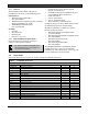
D7212GV2 | Operation and Installation Guide | Contents . Contents 1.0 2.0 2.1 2.2 3.0 3.1 3.1.1 3.1.2 3.2 3.3 3.3.1 3.3.2 3.3.3 3.3.4 3.3.5 3.3.6 3.3.7 3.3.8 3.3.9 3.3.10 3.3.11 3.3.12 3.3.13 3.3.14 3.3.15 3.3.16 4.0 4.1 4.2 4.3 4.4 4.5 4.5.1 4.5.2 4.5.3 4.5.4 4.5.5 4.6 4.6.1 4.6.2 4.6.3 4.6.4 4.6.5 4.7 Introduction....................................................... 6 Lightning Strikes .............................................. 7 Effects.............................................................
D7212GV2 | Operation and Installation Guide | 9.1.2 9.1.3 9.1.4 9.1.5 9.2 9.3 9.3.1 9.3.2 9.3.3 9.3.4 9.3.5 9.3.6 9.3.7 9.3.8 9.4 9.4.1 9.4.2 9.4.3 9.4.4 9.4.5 9.4.6 9.4.7 9.5 10.0 10.1 10.1.1 10.1.1 10.1.2 10.1.3 11.0 11.1 11.2 11.2.1 11.2.2 11.3 11.4 11.4.1 11.4.2 11.4.3 11.4.4 12.0 12.1 12.2 12.3 4 POPEX Modules ..............................................33 Missing Conditions...........................................33 Extra Point Events............................................
D7212GV2 | Operation and Installation Guide | . Figures Figure 1: Figure 2: Figure 3: Figure 4: Figure 5: Figure 6: Figure 7: Figure 8: Figure 9: Figure 10: Figure 11: Figure 12: Figure 13: Figure 14: Figure 15: Figure 16: Figure 17: Figure 18: Figure 19: Figure 20: Figure 21: Figure 22: Figure 23: Figure 24: Figure 25: Figure 26: Figure 27: Figure 28: Figure 29: Figure 30: Figure 31: System Configuration ................................. 8 Enclosure Mounting..................................
D7212GV2 | Operation and Installation Guide | 1.0 Introduction 1.0 Introduction This manual addresses the operation and installation of the D7212GV2 Control Panel only. Throughout this guide, the words “control panel” refer to the D7212GV2 Control Panel. To obtain any of the documents in Table 1, contact Bosch Security Systems, Inc. Technical Support and request the documentation by its corresponding part number.
D7212GV2 | Operation and Installation Guide | 2.0 Lightning Strikes . 2.0 Lightning Strikes The control panel is designed to significantly reduce electromagnetic interference and malfunction generally caused by lightning. 2.1 Effects Any electronic system can be struck directly by lightning or be adversely affected by a lightning strike near the system.
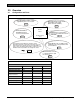
D7212GV2 | Operation and Installation Guide | 3.0 Overview 3.0 Overview 3.1 Configuration and Parts Figure 1: System Configuration Each D8128D OctoPOPIT combines eight POPIT points in one module. D8129 OctoRelay provides alarm and auxilliary relay output. (Other functions available.) Control Panel D8125, D8125INV, or D8125MUX Interface used for point expansion. On-Board Points 1 to 8 Use keypads or keyswitches to arm the control panel by area. Each control panel can have up to four areas.
D7212GV2 | Operation and Installation Guide | 3.0 . 3.1.1 • Parts List The D7212GV2 Control Panel is shipped preassembled from the factory with the following parts: Literature Pack • D7212GV2 Program Record Sheet (P/N: F01U003803) • 9000/G/GV2 Series Technical Service Note: UL Smoke Detector Compatibility (P/N: 33284) • 7000/9000 Series Point Chart Label (P/N: 79-06660-000) Assembly • PC board • Faceplate shield • Mounting skirt • One #6 x 1/4-in. screw 3.1.
D7212GV2 | Operation and Installation Guide | 3.0 Table 3: Compatible Accessories (continued) Model D1255W D1256 D1257 D1260/D1260B1 D1640 D8004 D8125 D8125MUX D8125INV2 D8128D D8129 D8130 D8132 D9127U/T D9131A ZX776Z ZX794Z ZX865 ZX938Z ZX970 1 2 Overview Title Text Keypad (white) Fire Keypad (Command Center) Fire Alarm Annunciator Keypads 16.
D7212GV2 | Operation and Installation Guide | 3.0 . 3.3.5 Points The Bosch Security Systems, Inc. D7212GV2 Control Panel provides up to 40 points of protection. Point programming parameters determine the control panel’s response to open and shorted conditions on the sensor loop for the point. Several options allow individual point programming to custom-fit the protection to the installation. Points 1 to 8 are located on the circuit board (on-board points). They are standard sensor loops.
D7212GV2 | Operation and Installation Guide | 3.0 Table 5: Model D1255/ D1255B/ D1255RB D1256/ D1256RB D1257/ D1257RB D1260/ D1260B D720/ D720B 3.3.
D7212GV2 | Operation and Installation Guide | 3.0 Overview . • • • Programmable relay output using the D8129 OctoRelay Module Opening and closing windows Skeds (scheduled events) Bosch Security Systems, Inc.
D7212GV2 | Operation and Installation Guide | 4.0 Installation 4.2 4.0 Installation 4.1 Mount the control panel assembly in any of the Bosch Security Systems, Inc. enclosures listed: Installation Preparation This section contains a general installation procedure and refers to other sections of the document for detailed instructions.
D7212GV2 | Operation and Installation Guide | 4.0 Installation . 4.4 1. 2. 3. Installing the Control Panel Place the control panel over the inside back of the enclosure, aligning the large rectangular openings of the mounting skirt with the mounting hooks of the enclosure. Slide the control panel down so that it hangs on the hooks. Refer to Figure 2, Item 2 on page 14. Remove the tape from the #6 x 1/4-in. screw in the mounting tab on the control panel.
D7212GV2 | Operation and Installation Guide | 4.0 4.5.3 Enabling Ground Fault Detection Installation Figure 4: To enable the Ground Fault Detect Enable feature: 1. Lock (close) the S4 Ground Fault Detect Pin on the control panel (Figure 4). Ground Fault Detect (S4) F01U003800-01 Incorrect wiring will damage this equipment. Suitable for dry indoor use only. Devices powered by the AUX power output must be supervised. LEDs Off When Normal Charging Status YEL Low Battery - 12.
D7212GV2 | Operation and Installation Guide | 4.0 . 4.5.5 Locking the Reset Pin 4.6 Locking the reset pin disables the control panel (Figure 6). When the control panel is disabled, the system ignores the keypads and points. CALL FOR SERVICE appears in keypad displays when the pin is locked down. On-board relays (Terminals 6 and 7) and off-board relays deactivate when the control panel is reset. Terminal 8 has power when the relay is deactivated. Activation interrupts power at that terminal.
D7212GV2 | Operation and Installation Guide | 4.0 4.6.3 Installing Modules and Relays 1. Power down the unit by unplugging the transformer and disconnecting the battery. Always power down the unit when installing modules or relays, or when making wiring connections to the control panel. 2. Install and wire any modules required for the installation as described in the module’s installation instructions.
D7212GV2 | Operation and Installation Guide | 4.0 Installation . 4.10 Service Walk Test The Service Walk Test differs from the standard Walk Test. In the standard Walk Test, POPITs whose switches are set for a point number not programmed in the control panel do not appear in the test. In the Service Walk Test, POPITs whose switches are set for a point number that is not programmed in the control panel do appear in the test.
D7212GV2 | Operation and Installation Guide | 4.0 Figure 7: Installation Service Walk Test Flow Chart SERVICE WALK? ENT 40 PTS TO TEST ESC Test a device POINT TEXT (Text displays for 60 seconds) 39 PTS TO TEST ESC Test a device POINT TEXT (Text displays for 60 seconds) 38 PTS TO TEST ESC Test a device POINT TEXT 1 PTS TO TEST ESC Test a device 0 PTS TO TEST IDLE TEXT ESC VIEW UNTESTED? ENT # PTS UNTESTED NEXT ESC ESC POINT TEXT 20 Bosch Security Systems, Inc.
D7212GV2 | Operation and Installation Guide | 5.0 Power Supply . 5. 5.0 Power Supply 5.1 Primary Power Terminals 1 and 2 5.1.1 Primary (AC) Power Circuit The primary source is a 16.5 VAC, 40 VA, internallyfused transformer (Bosch Security Systems, Inc. Model D1640). The control panel draws 200 mA when idle and 500 mA when in an alarm state. The total available auxiliary current is 1.4 A. Transient suppressors and spark gaps protect the circuit from power surges.
D7212GV2 | Operation and Installation Guide | 5.0 4. Power Supply Connect the red battery lead to Terminal 5, and then to the positive (+) side of the battery. Caution: The battery terminals and wire are not power limited. A 6.4 mm (0.250 in.) space must be maintained between the battery terminals, battery wiring, and all other wiring. Battery wiring cannot share the same conduit, conduit fittings, or conduit knockouts with other wiring. Refer to Figure 8. Warning: High current arcs are possible.
D7212GV2 | Operation and Installation Guide | 5.0 . 5.2.3 Replacing the Battery Figure 9: Power Supply Charging and Battery LEDs Replace batteries every 3 to 5 years under normal use. Record the date of installation directly on the battery. Caution: Exceeding the maximum output ratings or installing the transformer in an outlet that is routinely switched off causes heavy discharges. Routine heavy discharges can lead to premature battery failure.
D7212GV2 | Operation and Installation Guide | 5.0 Power Supply A shorted battery condition is created either by a shorted cell inside the battery or by a short on Terminals 4 and 5. A shorted battery might cause the control panel to operate in an unsafe way. This condition generates WATCHDOG RESET reports. 5.2.6 Battery Discharge and Recharge Schedule Table 7: Battery Discharge and Recharge Schedule Discharge Cycle AC Off: 13.9 VDC: 13.8 VDC: 12.0 VDC: < 10.0 VDC: Recharge Cycle AC On: 13.
D7212GV2 | Operation and Installation Guide | 6.0 Power Outputs . 6.0 Power Outputs 6.1 Circuit Protection Three self-resetting circuit breakers protect the control panel from short circuits on the continuous and programmable power outputs. If the control panel is programmed for power supervision and a short circuit occurs on one of the power outputs, the control panel sends a BATTERY LOW or BATTERY MISSING for Bosch Security Systems, Inc. Modem IIIa2 Communication Format, or TROUBLE ZN 9 for BFSK.
D7212GV2 | Operation and Installation Guide | 6.0 • Point Assignments section to confirm that each point is programmed for the expected local response. 6.4.2 Terminals 6 and 7 When activated, Terminals 6 (Relay A) and 7 (Relay B), provide positive (+) 10.2 VDC to 13.9 VDC power output. Use the power at Terminals 6 and 7 to power bells, siren drivers, piezoelectric fire sounders, electronic horns, or other devices. Programming determines the format of the output and the conditions that activate it.
D7212GV2 | Operation and Installation Guide | 7.0 Telephone Connections . 7.0 Telephone Connections 7.1 Registration Figure 10: RJ31X Wiring RING (red) R1 R The Bosch Security Systems, Inc. D7212GV2 Control Panel is registered with the Federal Communication Commission (FCC) under Part 68, for connection to the public telephone system using an RJ31X or RJ38X jack installed by the local telephone company.
D7212GV2 | Operation and Installation Guide | 7.0 7.5 Phone LED (Red) The red Phone LED illuminates when the control panel seizes the telephone line and remains illuminated until the control panel returns the telephone line. Refer to Figure 11 on page 27 for the location of the red LED. 7.6 Operation Monitor LED (Green) The green Operation Monitor LED indicates the operation of the central processing unit (CPU). When the CPU is operating normally, the LED flashes 0.5 sec on, 0.5 sec off.
D7212GV2 | Operation and Installation Guide | 8.0 On-Board Points . 8.0 On-Board Points 8.1 Terminals 11 to 22 Description The control panel provides eight on-board points. Each point functions independently and does not interfere with the operation of the others. The control panel monitors the sensor loops for normal, shorted, or open conditions between an input terminal (11, 13, 14, 16, 17, 19, 20, or 22) and any of the point common terminals (12, 15, 18, and 21).
D7212GV2 | Operation and Installation Guide | 8.0 8.4 Point Response Time On-Board Points 8.5 The control panel scans on-board and off-board point sensor loops every 300 ms. The Debounce program item in the Point Assignment section of the software determines point response time by setting the number of times the control panel scans a point before generating an alarm. The debounce count can range from 2 to 15; therefore, point response time ranges from 600 ms to 4.5 sec. The Bosch Security Systems, Inc.
D7212GV2 | Operation and Installation Guide | 8.0 On-Board Points . Figure 13: Rothenbuhler 5110/4001-42 High Security Bell Wiring Configuration 2 1 3 1 6 0.64 mm (1/4 in.) minimum distance 4 5 7 8 9 + - + - 10 10 11 12 11 13 14 16 123456789- 15 17 Self-contained vibration sensor Control panel Accessory modules High line security module 4001-42 Balanced Line Module 5110 Bell D133 Relay Zone input D122 Battery Harness* Bosch Security Systems, Inc.
D7212GV2 | Operation and Installation Guide | 8.
D7212GV2 | Operation and Installation Guide | 9.0 Off-Board Points . 9.0 Off-Board Points 9.1 Point (Zonex) Bus: D7212GV2 Terminals 9.1.1 POPIT Modules The D7212GV2 can use point of protection input transponder (POPIT) modules to provide a maximum of 32 offboard points, bringing the total number of points the D7212GV2 can monitor to 40. Each off-board point requires a POPIT Module. 9.1.
D7212GV2 | Operation and Installation Guide | 9.
D7212GV2 | Operation and Installation Guide | 9.0 Off-Board Points . Figure 15: Connecting the D8125 POPEX to the D7212GV2 Control Panel 2 RED Pin Battery amming Low Battery 4 D9127U/T 3 E CONNECTIONS 1 2 CLASS 2 TRANS 16.5 VAC 40 VAC Model D1640 Internally Fuse Requires Unsw Do Not Share 3 + AUX PO 4 BATTERY N 5 Maximum Charging Current 1.4 Amps.
D7212GV2 | Operation and Installation Guide | 9.0 9.3 Installing the D8125 POPEX Module For information on the Multiplex Bus Interface, refer to the D8125 Multiplex Bus Interface Operation and Installation Guide (P/N: 36796). Save the POPIT Label Sheets: The D8125 is packaged with two sets of POPIT label sheets. One set is marked “Bank 1” for use with the D7412GV2 and D7212GV2. The other set is marked “Bank 2” for use with the D9412GV2 and D9112. Use the Bank 1 sheet later to label the POPITs.
D7212GV2 | Operation and Installation Guide | 9.0 . 9.3.4 Wiring Data Expansion Loops to POPEX Modules Each POPEX Module has two positive (+) and two negative (-) data expansion loop terminals. Up to 32 POPITs can be connected to one D8125 on the D7212GV2 (refer to Figure 15 on page 35). To connect the data expansion loops to the D8125 POPEX Module: 1. Connect the positive (+) data terminal from the first POPIT on the data expansion loop to one of the D8125’s positive (+) terminals. 2.
D7212GV2 | Operation and Installation Guide | 9.0 Off-Board Points Figure 16: Program Record Sheet 9.3.8 POPIT Labels 9.4 D8128D OctoPOPIT Module D7212GV2 off-board points are numbered 9 to 40. Two sheets of peel-off POPIT labels are supplied with the D8125 POPEX Module. Use the sheet marked “Bank1” for Points 9 to 40. Each label has two parts. Place the smaller part, with only the point number, on the chip. Place the larger part, with the switch settings, on the base of the POPIT.
D7212GV2 | Operation and Installation Guide | 9.0 . The D8128D is also suitable for fire supervisory applications, such as indicating circuit supervision (using the D192G Bell Circuit Supervision Module), sprinkler supervision, and valve tamper protection. Use the D125B for two-wire smoke detectors. 9.4.3 1. Set the OctoPOPIT switches. Refer to Section 9.4.4 Setting the OctoPOPIT Switches. 2. Physically mount the OctoPOPIT in the enclosure. Refer to Section 9.4.5 Mounting OctoPOPITs on page 40. 3.
D7212GV2 | Operation and Installation Guide | 9.0 Table 15: Switch 5 Settings for Line Termination Is a D8125 POPEX Module connected? No Yes Switch 5 Setting(s) on D8128D OctoPOPIT(s) Set Switch 5 of only one D8128D to ON Set Switch 5 of all D8128Ds to OFF Off-Board Points 9.4.6 Warning: Disconnect all power to the control panel before beginning any work with the internal components. Serious injury could result from electrical shock. 1. Power down the control panel: a.
D7212GV2 | Operation and Installation Guide | 9.0 Off-Board Points . Figure 18: Connecting D8128D OctoPOPITs to the D7212GV2 1 First Address on ZONEX Bus 1 2 1 First Address on ZONEX Bus 1 2 RED Pin Battery amming Low Battery E CONNECTIONS CLASS 2 TRANS 16.5 VAC 40 VAC Model D1640 Internally Fuse Requires Unsw Do Not Share 1 2 3 + AUX PO 4 BATTERY N Maximum Charging Current 1.4 Amps.
D7212GV2 | Operation and Installation Guide | 9.0 Off-Board Points ® Using Molex Connectors Each D8128D Module is supplied with a 30 cm (12 in.) female-to-female Molex cable assembly. P1 and P2 are Molex connectors that parallel the COM, IN, OUT, and +12 VDC terminals on the terminal strip.
D7212GV2 | Operation and Installation Guide | 9.0 . 9.4.7 OctoPOPIT Sensor Loops Figure 20: D8128D OctoPOPIT Sensor Loops Only the resistance on the loop limits the number of normally-open or normally-closed detection devices each sensor loop can supervise. Resistance on each sensor loop must be less than 100 Ω with the detection devices connected. 1 Certain UL and NFPA applications can limit the number of detection devices. Consult the appropriate UL or NFPA standards.
D7212GV2 | Operation and Installation Guide | 10.0 D8129 Restricted for Fire Systems: D8129 relay outputs are not supervised and cannot be used in fire or combined fire and burglary installations for primary indicating devices. 10.0 Off-Board Relays 10.1 Off-Board Relays D8129 OctoRelay Use the D8129 OctoRelay to add relay outputs to the system in groups of eight. The D7212GV2 allows up to 24 relay outputs. Review Section 6.
D7212GV2 | Operation and Installation Guide | 10.0 Off-Board Relays . 10.1.1 Relay Outputs Relay outputs can activate when you are setting the OctoRelay switches or programming the control panel. Disconnect equipment connected to relay outputs when you perform these functions. Each OctoRelay output provides a Form C dry contact rated for 1.0 A at 12 VDC. Normally-open, common, and normally-closed terminals are available for each relay output.
D7212GV2 | Operation and Installation Guide | 11.0 Arming Devices 11.2.1 Assigning an Address for the Keypad 11.0 Arming Devices 11.1 Description Keypads, maintained or momentary contact keyswitches, or a combination of the two are used to arm and disarm areas. The control panel can contain up to four areas. Refer to 3.3.6 Areas and Accounts on page 11 for a description of areas. 11.2 Switches on the keypad assign an address (1 to 8).
D7212GV2 | Operation and Installation Guide | 11.0 . Wire Limits for Individual Devices Arming Devices Refer to the installation instructions for each device for wire length specifications. The control panel and the D8132 (or other power supply) must share COMMON. Extra Power for More Keypads Figure 22 shows the common form of the The D1255 Command Center draws 104 mA when idle. It draws 206 mA with the keys lit and the sounder activated. Review Section 6.
D7212GV2 | Operation and Installation Guide | 11.0 11.3 D279A Independent Zone Control Any on-board or OctoPOPIT point can be programmed so that the D279A Independent Zone Control operates as independent point control (arming and disarming the point). Refer to Point Assignments in the D7212GV2 Program Entry Guide (P/N: F01U003804) for programming information. Refer to the D279A Operation and Installation Instructions (P/N: 46458) for wiring and operation instructions. 11.4 Keyswitch 11.4.
D7212GV2 | Operation and Installation Guide | 12.0 SDI Devices . 12.3.1 Switch Settings 12.0 SDI Devices 12.1 Description The D7212GV2 Control Panel can support a number of accessory devices from the SDI Bus using Terminals 29 through 32. Some devices include the D1255RB and D1255 Keypads (refer to Section 11.0 Arming Devices on page 46), D9131A Parallel Printer Interface Module, DX4010i RS-232 Serial Interface Module, and DX4020 Network Interface Module. 12.
D7212GV2 | Operation and Installation Guide | 12.0 The DX4010i can be installed up to 305 m (1000 ft) from the control panel, using 0.8 mm (22 AWG) wire. The DX4010i was not investigated by UL. Do not use DX4010i in UL Listed installations. The D9133 can be installed up to 305 m (1000 ft) from the control panel using 1.2 mm (18 AWG) wire. The D9133 was not investigated by UL. Do not use the D9133 in UL Listed installations. 12.4.
D7212GV2 | Operation and Installation Guide | 13.0 . 12.5.2 Network Interface Modules The Bosch Security Systems, Inc. DX4020 Network Interface Module is a four-wire powered SDI device that provides connection for two-way communication over Ethernet networks to the D7212GV2. For programming information on enhanced communications, refer to the D7212GV2 Program Entry Guide (P/N: F01U003804). The DX4020 can be installed up to 305 m (1000 ft) from the control panel using 0.8 mm (22 AWG) wire.
D7212GV2 | Operation and Installation Guide | 14.0 D7212GV2 Faceplate 14.0 D7212GV2 Faceplate Figure 28: D7212GV2 Faceplate F01U003800-01 Incorrect wiring will damage this equipment. Suitable for dry indoor use only. Devices powered by the AUX power output must be supervised. LEDs Off When Normal YEL Charging Status Low Battery - 12.
D7212GV2 | Operation and Installation Guide | Appendix A: System Wiring Diagrams, Issue A . Appendix A: System Wiring Diagrams, Issue A Figure 29: D7212GV2, Power Supply Side 1 D113 BAT 2- CHGR- BAT 2+ VAUX+ BAT 1- SUPV BAT 1+ CHGR+ 2 4 3 2 2 6 2 CLASS 2 TRANSFORMER 16.5 VAC 40 VA 60 Hz Model D1640 Internally Fused - Do Not short Requires Unswitched Outlet Do Not Share With Other Equipment 7 5 D7212GV2 + AUX POWER BATTERY NEGATIVE ONLY Maximum Charging Current 1.4 Amps.
D7212GV2 | Operation and Installation Guide | Appendix A: System Wiring Diagrams, Issue A Figure 30: D7212GV2, Input Points and Peripheral Devices CLASS 2 TRANSFORMER 16.5 VAC 40 VA 60 Hz Model D1640 Internally Fused - Do Not short Requires Unswitched Outlet Do Not Share With Other Equipment D7212GV2 + AUX POWER BATTERY NEGATIVE ONLY Maximum Charging Current 1.4 Amps.
D7212GV2 | Operation and Installation Guide | Appendix A: System Wiring Diagrams, Issue A . Figure 31: D7212GV2, SDI Devices D7212GV2 PERIPHERAL DEVICE CONNECTIONS PERIPHERAL DEVICE CONNECTIONS RED POWER + RED POWER + YELLOW YELLOW DATA BUS A DATA BUS A GREEN GREEN DATA BUS B DATA BUS B BLACK BLACK COMMON COMMON NFPA NFPA Style 3.5 Style 3.
D7212GV2 | Operation and Installation Guide | Appendix B: Point Address Chart Appendix B: Point Address Chart Place the labels on the base of the POPIT. Do not attach labels to the POPIT cover. A bullet (•) in the switch column indicates that the switch is set to ON. Use D8127 or D9127 POPITs for Points 9 to 40. D8127 POPITs have DIP switches 1 to 6; D9127 POPITs have DIP switches 0 to 6.
D7212GV2 | Operation and Installation Guide | Appendix B: Point Address Chart . Notes Bosch Security Systems, Inc.
D7212GV2 | Operation and Installation Guide | Appendix B: Point Address Chart Notes 58 Bosch Security Systems, Inc.
D7212GV2 | Operation and Installation Guide | Specifications . Specifications Table 23: Specifications Voltage Input (Power Supply) Primary: Terminals 1 and 2 16.5 VAC 40 VA class 2 plug-in transformer (D1640) Secondary: Terminals 4 and 5 Sealed lead-acid rechargeable battery (12 VDC, 7 Ah or 12 VDC, 17.2 or 18 Ah). The control panel supports up to two 12 VDC, 7 Ah batteries using the D122 Dual Battery Harness or two D1218 (12 VDC, 17.2 or 18 Ah) batteries using a D122.
Bosch Security Systems, Inc. 130 Perinton Parkway Fairport, NY 14450-9199 Customer Service: (800) 289-0096 Technical Support: (888) 886-6189 © 2007 Bosch Security Systems, Inc.