
Installation Guide

D7212GV3 | Operation and Installation Guide | 9.0 Off-Board Points
.
Bosch Security Systems, Inc. | 10/10 | F01U143079-03 41
Using Molex Connectors
Each D8128D Module is supplied with a 30 cm (12 in.) female-to-female Molex cable assembly.
P1 and P2 are Molex connectors that parallel the COM, IN, OUT, and +12.0 VDC terminals on the terminal
strip. In installations with multiple D8128Ds, use these connectors (as opposed to terminals) with the supplied
cable; however, when connecting D8128D Modules directly to the control panel, the terminal strip is easier to
use.
The Molex connectors provided are "keyed" (Molex plug can only fit in one direction). Ensure the connector is
attached correctly: the red wire is on the bottom of P1 (or P2) and the black wire is on the top.
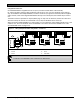
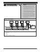
When connecting multiple D8128Ds to a control panel, you can connect the control panel terminals to P1 or the
COM, IN, OUT, and +12V terminals on the first D8128D. Then connect P2 of the first D8128D to P1 of the
second D8128D and so on (Figure 17).
Figure 17: Wiring Multiple D8128Ds Using Molex
®
Connectors
COM
IN OUT+12V
P1
P2
COM
IN OUT+12V
P1
P2
28
27
26
25
24
23
COM
IN OUT+12V
P1
P2
6
6
6
5
4
1
2
3
1 - D7212GV3 Control Panel
2 - Yellow
3 - Green
4 - Black
5 - Red
6 - D8128D
A maximum of four D8128Ds can be installed on the D7212GV3.