DANESMOOR UTILITY 12/14, 15/19, 20/25, 26/32, 32/50, 50/70 CONVENTIONAL FLUE AND ROOM-SEALED BF FLOOR STANDING OIL-FIRED PRESSURE JET APPLIANCES INSTALLATION AND SERVICING INSTRUCTIONS Worcester supports the Benchmark code of practice THESE INSTRUCTIONS ARE TO BE LEFT WITH THE APPLIANCE This appliance must be installed and serviced by a competent person
Contents 1. 2. 3. 4. 5. 6. 7. 8. 9. 10. 11. 12. 13. 14. 15. 16. Installation Regulations ...........................................Page 2 General Information .................................................Page 2 Technical Data...........................................................Page 3 Siting the Appliance .................................................Page 6 Removal of the Cabinet............................................Page 6 Air Supply.......................................................
. Technical Data Table 1 Model POWER SUPPLY IP RATING HEATING FLOW HEATING RETURN FUEL LINE CF RS 12/14 230V 50 Hz 15/19 230V 50 Hz IP 20 1 in. BSP 1 in. BSP IP 20 1 in. BSP 1 in. BSP SPECIFICATIONS 20/25 230V 50 Hz IP 20 1 in. BSP 1 in. BSP 26/32 230V 50 Hz 32/50 230V 50 Hz 50/70 230V 50 Hz IP 20 11/4 in. BSP 11/4 in. BSP IP 20 11/2 in. BSP 11/2 in. BSP IP 20 11/2 in. BSP 11/2 in. BSP 1 1 1 /4 in. BSP /4 in. BSP /4 in. BSP /4 in.
12/14 Table 2. Electro Oil Inter B9A Burner (See Fig. 18) NOMINAL BOILER RATING AT NORMAL OPERATING TEMPERATURE Fuel 28 Sec. Kerosene 28 Sec. Kerosene Nozzle Pump Pressure (p.s.i.) 0.40 60°ES 0.50 60°ES 130 100 Fuel Flow Rate Kg/h l/h 1.11 1.41 1.30 1.64 Flue Gas Temp. (°C)** 180 195 %CO2 10.0 11.5 Approx. Air Setting 6.0 7.0 Appliance Input Output kW Btu/hr kW Btu/hr 13.5 46,000 12 41,000 15.5 53,000 14 48,000 15/19 Table 3. Electro Oil Inter B9B Burner (See Fig.
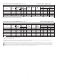
32/50 Table 7. Electro Oil Inter B20C Burner (See Fig. 22) Conventional Flue Appliance (CF) NOMINAL BOILER RATING AT NORMAL OPERATING TEMPERATURE Fuel 28 Sec. Kerosene* 28 Sec. Kerosene* 28 Sec. Kerosene* 35 Sec. Gas Oil* 35 Sec. Gas Oil* Nozzle Pump Pressure (p.s.i.) 0.85 60°ES 1.20 60°S 1.35 60°S 0.85 60°S 1.0 60°S 160 150 150 210 260 Fuel Flow Rate Kg/h l/h 2.94 3.72 3.77 4.76 4.6 5.81 3.82 4.6 4.66 5.61 Flue Gas Temp. (°C)** 165 190 220 190 210 %CO2 12.0-12.5 12.0-12.5 12.0-12.5 12.0-12.5 12.
ROOM SEALED BALANCED FLUE MODEL (RS) 6.4 The appliance does not require a separate vent for combustion air. 6.5 Installation in cupboards or compartments require permanent vents for cooling purposes, one at high level and one at low level, either direct to outside air or to a room. Both vents must pass to the same room or be on the same wall to the outside air. The minimum air vent free area is given in Table 11. 6.
Fig. 2. Conventional Flue Appliance (CF/LLD).
Fig. 3. Room Sealed Balanced Flue Appliance (RS).
Down-draught conditions will adversely affect the operation of the boiler and must be avoided. Where possible the flue should be extended beyond the apex of the roof and should always be taken beyond the eaves of the building. Where down-draught is experienced a suitable anti down-draught terminal should be fitted to the flue termination. The natural flue draught must be checked in the flue pipe immediately above the appliance or in the hole provided in the flue outlet plate.
Fig. 6. Room Sealed Balanced Flue Terminal Installation. X = 180mm Maximum X (a) Rear Discharge 4" to 7" Single Skin Wall. For use with non-standard/single skin walls up to 182.mm thick. Where noise emission from the flue terminal is likely to be of concern, it is recommended that the standard 12 in. terminal is used and the appliance stood away from the wall to take up the extra terminal body length. X = 327mm Maximum X 270mm FLUE GUARD 340mm (b) Rear Discharge 7" to 12" Wall.
3. The terminal must not cause an obstruction nor the discharge cause a nuisance as a result of either flue gases or terminal noise. Fig. 8. Terminal guard Minimum dimensions. 4. If the terminal is fitted within 1m of a plastic or painted gutter or within 500 mm of painted eaves then an aluminium or stainless steel shield at least 1m long should be fitted to protect the surface. 265 5.
gns shown in Fig. 8. 8. Oil Supply Fig. 9. Oil Pump. 1 INLET A. Danfoss BFP 41. (See Figs. 9, 10 and 11). 8.1 Plastic or steel tanks should be installed to BS5410. A steel tank should also conform to BS799: part 5 and be arranged with a slope of 1 in 24 away from the outlet valve with a sludge cock at its lower end. 8.2 Do not use galvanised steel tanks or pipework for the oil supply system. 8.3 Do not use soldered joints in the oil supply pipework as this could cause a hazard in the case of a fire. 8.
TABLE 14 Single Pipe Suction Lift with De-aerator MAXIMUM ALLOWABLE PIPE RUN FROM TANK TO DE-AERATOR (metres) 5.0 (kg/h) 100 95 80 70 60 45 35 25 6 mm inside dia. pipe (8 mm O.D. copper) 55 45 40 35 30 25 15 10 10.0 (kg/h) 10.0 (kg/h) 26 23 20 17 14 11 8 5 8 mm inside dia. pipe (10 mm O.D. copper) 100 100 90 75 65 50 35 20 Fig. 10. Oil Supply. Wall Full base (for plastic tanks) Filter Isolating valve Isolating valve Non return valve (b) Double pipe system.
Fig. 11. Oil Pipe Installation. Fig. 12. Typical Open Vent Fully Pumped System (Honeywell ‘Y’ plan).
Fig. 13. Typical fully pumped sealed system (Honeywell ‘Y’ plan). Automatic air vent Domestic hot water cylinder Diverting valve Safety valve N.B. A drain cock should be installed at the lowest point of the heating circuit Pressure gauge Pump Radiator Expansion Vessel Boiler To system filling device (see Fig.14) Automatic bypass valve to be fitted where thermostatic radiator valves are fitted on all radiators Fig. 14.
. 9. Heating And Hot Water System 10. Electrical The heating and hot water system must be provided in accordance with the current Building Regulations. 9.1 The appliance is suitable for connection to all conventional indirect hot water systems utilising an indirect double feed cylinder. 9.2 The flow and return sockets are located at the rear of the appliance, two at high level (flow) and two at low level (return).
Fig. 15. Wiring Diagram (Standard). Fig. 16. Pre-wired Remote ‘Y’ Plan or ‘S’ Plan. Remote Pre-wired Junction Box 10 WAY JUNCTION BOX External Timer Pump System Water Valves Room Stat Tank Stat Mains Wiring 230V 50Hz (5 amp fuse) If the system is fully pre-wired at a junction box remotely from the boiler it can be easily connected into the Worcester Utility Oil Boiler. NOTE: If a frost thermostat is required it can be wired to the remote junction box.
5. The primary system should be flushed and treated in accordance with the recommendations of BS 7593. 11. Installation 11.5 Oil supply installation (See Figs. 9 to 11). NOTE: Never route the oil supply pipe/hose directly below the combustion chamber base. NOTE: Connection of rigid copper pipe to the oil pump is not recommended. Connection to the oil pump should be made with flexible oil hoses. 11.
7. Draw off at least 2.5 litres of oil until a steady flow of clear uncontaminated oil can be seen and turn off the isolating valve. Note: This method may not be possible on some installations where a sub-gravity system is used. Where this problem arises bleed the system using the oil pump as described in Section 12 and remove and clean the oil pump filter to remove any debris collected as a result of installation. 11.
burner has gone to lockout. In this instance wait two minutes and press the lockout reset button to initiate another start sequence. Repeat the procedure until a flame is established. Note: Persistent lockout when running indicates a fault and a Service Engineer should be consulted. 12.11 Run the boiler for approximately 3 minutes and switch off checking that there is no after-spurting from the nozzle. This can be detected by oil saturation on the blast tube.
Fig. 19. Electro Oil Inter B9B Burner. (15/19 model) Locking screw Combustion head Combustion Head A Spark gap 2-2.5 mm 2 mm Photocell 10 mm Adjusting disc Transformer Draught tube Nozzle Nozzle block Output Dimension Pressure Adjustment Screw kW Head Type A 15 PL 6/7/21.5/10 3 mm 17 PL 6/7/21.5/10 5 mm Oil pump 19 PL 6/7/21.
Fig. 21. Electro Oil Sterling Burner. (26/32 model). Combustion Head Spark gap 2.5-3.0mm A 0mm 7.5mm Draught tube Output kW 26-32 Nozzle Nozzle block Dimension A 3.5mm Combustion Head PL 6/7/21.5/10 x 78 mm Fig. 22. Electro Oil Inter B20C Burner (32/50 model). Combustion Head PL 10/8/10/6/19/10 - E x 78mm 0mm Spark gap 2.5 to 3mm A Air guide (Remove at 50kW 28sec only) 7.5mm Blast tube Nozzle block Nozzle Output kW 32 41 50 41 50 Fuel 28sec. Kerosene 28sec. Kerosene 28sec. Kerosene 35sec.
Fig. 23. Electro Oil Inter B20B Burner. (50/70 model). Combustion Head (Type K x 94mm) (PL 21.5/10) Output kW 50 60 70 50 60 70 Fuel 28sec. Kerosene 28sec. Kerosene 28sec. Kerosene 35sec. Gas Oil 35sec. Gas Oil 35sec. Gas Oil Dimension (mm) A B 24 10 26 10 28 10 20 8 22 8 24 8 6. Check and clean the cap retainer (32/50 and 50/70 models). 7. Check and clean the baffles. 8. Check and clean the heat exchanger surface. 9. Check the heat shield (20/25, 26/32, 32/50 and 50/70 models). 10.
(b) Remove the burner box cover by pulling forwards to release the ball studs. This will be found easier by pulling on one side of the handle first to release two of the ball studs and then repeating on the other side. Take care not to pivot the remaining two ball studs too far around as this will cause damage to the spring clips. (c) Disconnect the burner plug-in connector by removing the electrical facia and pulling the three-pin connector free. Fig. 24 Slide the locating bush from the electrical box.
(c) Check that the impeller rotates freely. (d) Clean the air damper which is attached to the fan cover and check that the adjustment mechanism operates freely. (e) Re-assemble the components. Fig. 25. Location of cap retainer (32/50 and 50/70 models) and location of top baffle. (32/50 model only). Access Door 3. Remove the combustion head and thoroughly clean all deposits. Fig. 26. Mechanical Shut-off Valve. Top Baffle (32/50 model only) Cap Retainer Cap 4. Inspection of Mechanical Shut-off Valve.
located within the appliance case. A fire valve clip is provided for this purpose as shown in Figs 2 & 3. Test the operation of the fire valve to ensure that the mechanism operates and that the oil supply is completely isolated. NOTE: The fire sensing element must be located on the top face of the burner surround box on RS balanced flue models, as shown in Fig.3, to allow quick detection of a dangerous situation. 14.8 Recommission the Burner. 1.
Worn motor bearings. Replace motor. Worn pump. Replace. Pump noise. Air in pump. Noisy operation. Electrode settings incorrect. See installation instructions. High tension leads faulty. Electrical connections not properly made in control box. Fan out of balance. Replace fan. External controls not operating correctly. Faulty boiler thermostat. Replace if necessary. FAULTY BOILER OPERATION Electrodes broken. Open circuit ignition. IGNITION FAILURE Photocell filmed over. Clean.
www.worcester-bosch.co.uk Bosch Group Worcester, Bosch Group, Cotswold Way, Warndon, Worcester WR4 9SW. Telephone: 01905 754624. Fax: 01905 753130. Technical Helpline 08705 266241. Worcester, Bosch Group is a trading name of BBT Thermotechnology UK Limited. This booklet is accurate at the date of printing but will be superseded and should be disregarded if specifications and/or appearances are changed in the interests of continued improvement.