
Technical data


14.6 Clean the Boiler
1. Remove the boiler top access door by releasing the M10 nuts
and check the fibreglass rope seal. Replace the seal if necessary.
2. Remove the burner mounting flange by releasing the three
M10 nuts and check the fibre glass gasket, it is imperative that
this seal is in good condition. Replace the seal if necessary
(32/50 and 50/70 models only).
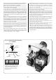
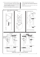
3. Remove and check the baffle retainer, where fitted (20/25,
26/32, 32/50 and 50/70 models). See Fig. 24.
4. Remove the baffles, clean and check their condition. Replace
any baffles considered to be badly corroded.
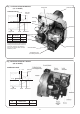
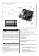
5. Remove and check the cap retainer, where fitted (32/50 and
50/70 models only). See Fig. 24d, 24e & 25.
6. Remove the cap (32/50 and 50/70 models only) and check
the ‘rocksulate’ gasket. Replace the seal if necessary.
7. Thoroughly clean all of the heat exchanger surfaces using a stiff
wire brush and vacuum clean all loose debris from the combustion
chamber. Take care not to damage the base insulation!
8. Remove and check the heat shield where fitted (20/25,
26/32, 32/50 and 50/70 models). (See Fig. 24).
9. Check the combustion chamber base insulation board and
replace if there is any sign of damage.
10. Check and clean the flue.
11. Replace the items in reverse order noting the baffle positions
shown in Fig. 24.
14.7 Fire Valve.
Check that a fire valve is fitted to the incoming oil line with the
body located outside the premises and the detection element
located within the appliance case. A fire valve clip is provided
for this purpose as shown in Figs 2 & 3. Test the operation of the
fire valve to ensure that the mechanism operates and that the oil
supply is completely isolated.
NOTE: The fire sensing element must be located on the top face of
the burner surround box on RS balanced flue models, as shown
in Fig.3, to allow quick detection of a dangerous situation.
14.8 Recommission the Burner.
1. Connect the flexible oil supply hose to the isolating valve and
tighten sufficiently to form a good seal. Where a double pipe
system is being used connect the oil return flexible hose to
return pipe fitting.
2. With the sponge O-ring gasket around the burner blast tube
insert the burner into the housing tube. Push the burner firmly
forward to compress the gasket and tighten the two locking
screws, using a 5mm Allen key.
Note: It is important that a good seal is made between the
burner and the boiler to prevent re-emission of the flue gases
from the combustion chamber to the burner inlet, or the room in
the case of a CF/LLD appliance.
3. On the RS balanced flue model feed the electrical lead back
through the hole in the burner surround housing (in the reverse
order to that described in 11.2) and fit the grommet into the hole
ensuring a seal is made.
4. Reconnect the electrical lead plug into the control box.
5. Turn on the oil supply at the service cock.
6. Recommission the burner as described in Section 12.
26
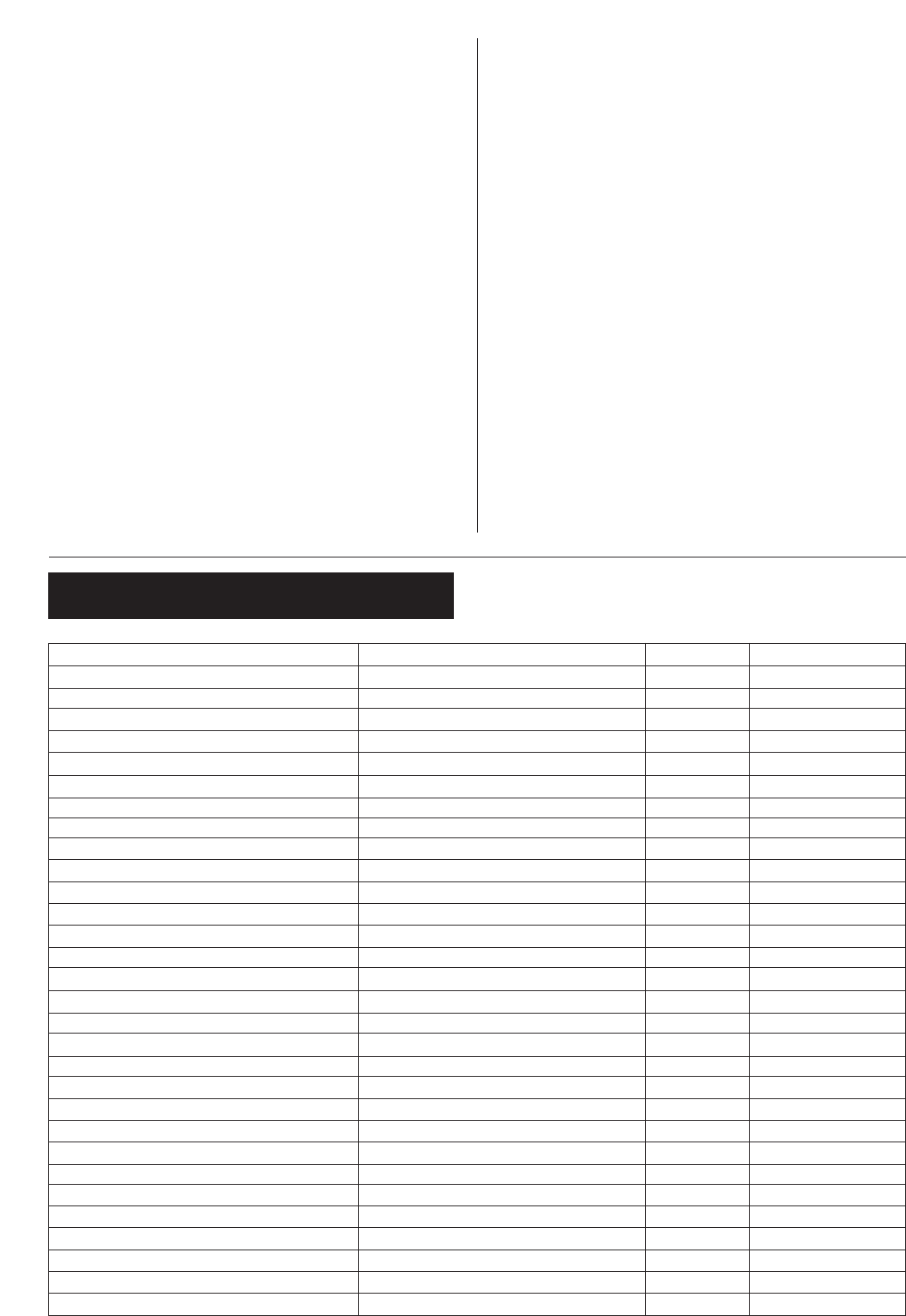
15. Short Parts List
Part Manufacturers Reference Qty Worcester Part No.
Burner for 12/14 Bentone B9A 1 8 716 104 431 0
B9A Combustion Head PL 6/7/21.5/10-E x 78mm 1 8 716 157 041 0
Burner for 15/19 Bentone B9B 1 8 716 142 705 0
B9B combustion Head PL 6/7/21.5/10 x 78mm 1 8 716 156 697 0
Burner for 20/25 Bentone B11C 1 8 716 104 432 0
B11C Combustion Head PL 10/4/24/10 x 78mm 1 8 716 142 784 0
Burner for 26/32 Bentone Sterling 40 1 8 716 142 700 0
Sterling 40 Combustion Head PL 6/7/21.5/10 x 78mm 1 8 716 156 697 0
Burner for 32/50 Bentone B20C 1 8 716 104 546 0
B20C Combustion Head PL10/8/10/6/19/10-E x 78mm 1 8 716 104 769 0
Burner for 50/70 Bentone B20B 1 8 716 104 547 0
B20B Break Plate PL 21.5/10 (type K) 1 8 716 156 518 0
B20B Blast Tube Type K x 94mm 1 8 716 142 739 0
Burner control 1. Control Box Satronic TF 832.3 1 8 716 156 648 0
B9, B11 and B20 Photocell Satronic MZ770 1 8 716 142 735 0
Sterling 40 Photocell Satronic MZ770 1 8 716 156 692 0
Control Box Base Satronic S01 S701 1 8 716 142 782 0
Ignition Electrode 1 8 716 142 752 0
Motor B9 AEG or Simel 70 W 1 8 716 156 597 0
Motor B11 and B20 AEG (FHP) 90W 1 8 716 142 732 0
Motor Sterling 40 AEG (FHP) 90W 1 8 716 156 645 0
Oil Pump B9 Danfoss BFP41L3 1 8 716 142 743 0
Oil Pump (B11, B20 and Sterling 40) Danfoss BFP11L3 1 8 716 142 736 0
Transformer Danfoss EBI 052F0030 (excludes cable) 1 8 716 156 696 0
Mechanical Shut-Off Valve 1 8 716 156 658 0
Flexible Oil Line Kit Worcester 1 8 716 156 663 0
Burner 'O' Shaped Gasket Worcester 1 8 716 140 902 0
Control Thermostat Siebe K36-P2312 1 8 716 142 309 0
Automatic Reset High Limit Thermostat Siebe LO7-P1022 1 8 716 142 311 0
Manual Reset High Limit Thermostat Siebe LM7-P5075 1 8 716 142 310 0