BM 2610033824 DDB181 02-14_DDB181 2/7/14 1:24 PM Page 1 IMPORTANT: Read Before Using IMPORTANT : Lire avant usage IMPORTANTE: Leer antes de usar Operating/Safety Instructions Consignes de sécurité/d’utilisation Instrucciones de funcionamiento y seguridad DDB181 Call Toll Free for Consumer Information & Service Locations Pour obtenir des informations et les adresses de nos centres de service après-vente, appelez ce numéro gratuit Llame gratis para obtener información para el consumidor y ubicaciones
BM 2610033824 DDB181 02-14_DDB181 2/7/14 1:24 PM Page 2 General Power Tool Safety Warnings Read all safety warnings and all instructions. Failure to follow the warnings ! WARNING and instructions may result in electric shock, fire and/or serious injury. SAVE ALL WARNINGS AND INSTRUCTIONS FOR FUTURE REFERENCE The term “power tool” in the warnings refers to your mains-operated (corded) power tool or battery-operated (cordless) power tool. Work area safety power tool.
BM 2610033824 DDB181 02-14_DDB181 2/7/14 1:24 PM Page 3 Battery tool use and care Disconnect the plug from the power source and/or the battery pack from the power tool before making any adjustments, changing accessories, or storing power tools. Such preventive safety measures reduce the risk of starting the power tool accidentally. Recharge only with the charger specified by the manufacturer.
BM 2610033824 DDB181 02-14_DDB181 2/7/14 1:24 PM Page 4 If the bit becomes bound in the workpiece, release the trigger immediately, reverse the direction of rotation and slowly squeeze the trigger to back out the bit. Be ready for a strong reaction torque. The drill body will tend to twist in the opposite direction as the drill bit is rotating. Do not use dull or damaged bits and accessories. Dull or damaged bits have a greater tendency to bind in the workpiece.
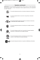
BM 2610033824 DDB181 02-14_DDB181 2/7/14 1:24 PM Page 5 Symbols IMPORTANT: Some of the following symbols may be used on your tool. Please study them and learn their meaning. Proper interpretation of these symbols will allow you to operate the tool better and safer.
BM 2610033824 DDB181 02-14_DDB181 2/7/14 1:24 PM Page 6 Symbols (continued) IMPORTANT: Some of the following symbols may be used on your tool. Please study them and learn their meaning. Proper interpretation of these symbols will allow you to operate the tool better and safer. This symbol designates that this tool is listed by Underwriters Laboratories. This symbol designates that this component is recognized by Underwriters Laboratories.
BM 2610033824 DDB181 02-14_DDB181 2/7/14 1:24 PM Page 7 Functional Description and Specifications Disconnect battery pack from tool before making any assembly, ! WARNING adjustments or changing accessories. Such preventive safety measures reduce the risk of starting the tool accidentally. Cordless Drill Driver GEAR SHIFTER ADJUSTABLE CLUTCH VENTILATION OPENINGS KEYLESS CHUCK FORWARD/REVERSING LEVER & TRIGGER LOCK RUBBERIZED GRIP FIG.
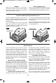
BM 2610033824 DDB181 02-14_DDB181 2/7/14 1:24 PM Page 8 Assembly Disconnect battery pack Do not use the power of the drill while grasping chuck to loosen or tighten bit. Friction burn or hand injury is possible if attempting to grasp the spinning chuck. ! WARNING from tool before making any assembly, adjustments or changing accessories. Such preventive safety measures reduce the risk of starting the tool accidentally. INSERTING BITS Move reverse switch lever to the center “OFF” position.
BM 2610033824 DDB181 02-14_DDB181 2/7/14 1:24 PM Page 9 Operating Instructions VARIABLE SPEED CONTROLLED TRIGGER SWITCH Your tool is equipped with a variable speed trigger switch. The tool can be turned "ON" or "OFF" by squeezing or releasing the trigger. The speed can be adjusted from the minimum to maximum nameplate RPM by the pressure you apply to the trigger. Apply more pressure to increase the speed and release pressure to decrease speed (Fig. 1).
BM 2610033824 DDB181 02-14_DDB181 2/7/14 1:24 PM Page 10 BRAKE When the trigger switch is released it activates the brake to stop the chuck quickly. This is especially useful in the repetitive driving and removal of screws. BUILT IN WORK LIGHT Your tool is also equipped with a light that turns on automatically when the switch is activated, for better visibility when drilling/driving (Fig. 1). INSERTING AND RELEASING BATTERy PACK Set Forward/Reversing lever to the center (off position).
BM 2610033824 DDB181 02-14_DDB181 2/7/14 1:24 PM Page 11 2. Drill same diameter as screw shank. FASTENING WITH SCREWS 1. Drill 2/3 diameter and 2/3 of screw length for soft materials, full length for hard materials. 3. Countersink same diameter as screw head. Adjustable Screw Drill Screw Apply a slight even pressure when driving screws. DRILLING METAL There are two rules for drilling hard materials. First, the harder the material, the greater the pressure you need to apply to the tool.
BM 2610033824 DDB181 02-14_DDB181 2/7/14 1:24 PM Page 12 RUNNING NUTS AND BOLTS Variable speed control must be used with caution for driving nuts and bolts with socket set attach ments. The technique is to start slowly, increasing speed as the nut or bolt runs down. Set the nut or bolt snugly by slowing the drill to a stop. If this procedure is not followed, the tool will have a tendency to torque or twist in your hands when the nut or bolt seats.
BM 2610033824 DDB181 02-14_DDB181 2/7/14 1:24 PM Page 13 Avertissements généraux concernant la sécurité des outils électroportatifs Veuillez lire tous les avertissements et toutes les consignes de sécurité. Si l'on ! AVERTISSEMENT n'observe pas ces avertissements et ces consignes de sécurité, il existe un risque de choc électrique, d'incendie et/ou de blessures corporelles graves. CONSERVEZ TOUS LES AVERTISSEMENTS ET TOUTES LES CONSIGNES DE SÉCURITÉ POUR RÉFÉRENCE FUTURE.
BM 2610033824 DDB181 02-14_DDB181 2/7/14 1:24 PM Page 14 Utilisation et entretien des outils électroportatifs Ne forcez pas sur l’outil électroportatif. Utilisez l’outil électroportatif qui convient à la tâche à effectuer. L’outil qui convient à la tâche fait un meilleur travail et est plus sûr à la vitesse pour lequel il a été conçu. Ne vous servez pas de l’outil électroportatif si son interrupteur ne parvient pas à le mettre en marche ou à l’arrêter.
BM 2610033824 DDB181 02-14_DDB181 2/7/14 1:24 PM Page 15 les accessoires. Ces mesures de sécurité préventives réduisent le risque d'une mise en marche accidentelle de l'outil. Placez-vous de manière à éviter d'être pris entre l'outil ou la poignée latérale et les murs ou les montants. Si le foret se coince ou grippe dans l'ouvrage, le couple de réaction de l'outil pourrait écraser votre main ou votre pied.
BM 2610033824 DDB181 02-14_DDB181 2/7/14 1:24 PM Page 16 Symboles IMPORTANT : Certains des symboles suivants peuvent être utilisés sur votre outil. Veuillez les étudier et apprendre leur signification. Une interprétation appropriée de ces symboles vous permettra d'utiliser l'outil de façon plus efficace et plus sûre.
BM 2610033824 DDB181 02-14_DDB181 2/7/14 1:24 PM Page 17 Symboles (suite) IMPORTANT : Certains des symboles suivants peuvent être utilisés sur votre outil. Veuillez les étudier et apprendre leur signification. Une interprétation appropriée de ces symboles vous permettra d'utiliser l'outil de façon plus efficace et plus sûre. Ce symbole signifie que cet outil est approuvé par Underwriters Laboratories. Ce symbole indique que ce composant est reconnu par Underwriters Laboratories.
BM 2610033824 DDB181 02-14_DDB181 2/7/14 1:24 PM Page 18 Description fonctionnelle et spécifications Débranchez le bloc-piles de l'outil avant d'effectuer tout assemblage ou réglage, ou de changer des accessoires. Ces mesures de sécurité préventives réduisent le risque d'une mise en marche accidentelle de l'outil. ! AVERTISSEMENT Perceuse/visseuse sans fil CHANGEMENT DE VITESSE EMBRAYAGE REGLABLE OUVERTURES DE VENTILATION MANDRIN SANS CLE LEVIER DE MARCHE AVANT/ARRIÈRE ET VERROUILLAGE DE GÂCHETTE FIG.
BM 2610033824 DDB181 02-14_DDB181 2/7/14 1:24 PM Page 19 Assemblage Débranchez le bloc-piles de l'outil avant d'effectuer tout assemblage ou réglage, ou de changer des accessoires. Ces mesures de sécurité préventives réduisent le risque d'une mise en marche accidentelle de l'outil. N'utilisez pas la puissance de la perceuse en saisissant le mandrin pour desserrer ou resserrer le foret. Si vous tentez de saisir le mandrin en rotation, vous pourriez être blessé à la main ou subir une brûlure de friction.
BM 2610033824 DDB181 02-14_DDB181 2/7/14 1:24 PM Page 20 Consignes de fonctionnement GÂCHETTE DE COMMANDE A VITESSE VARIABLE Votre outil est équipé d’une gâchette de commande à vitesse variable. Vous pouvez mettre le tournevis en marche ou à l'arrêt en appuyant sur la gâchette ou en la relâchant, suivant le cas. En fonction de la pression exercée sur la gâchette, il est possible de régler la vitesse dans les limites minimale et maximale spécifiées sur la plaquette emblématique.
BM 2610033824 DDB181 02-14_DDB181 2/7/14 1:24 PM Page 21 FREIN Le relâchement de la gâchette active le frein qui immobilise le mandrin en rapidité, ce qui est surtout pratique pour l’enfoncement et l’enlèvement répétitifs des vis. ÉCLAIRAGE D’APPOINT INTÉGRÉ Votre outil est également doté d’une lampe qui s’allume automatiquement quand on appuie sur la gâchette pour améliorer la visibilité lors du perçage/vissage (Fig. 1). Veillez toujours à bien serrer la vis de montage avant l'utilisation (Fig. 1).
BM 2610033824 DDB181 02-14_DDB181 2/7/14 1:24 PM Page 22 2. Percez le même diamètre que la tige de la vis. FIXATION À L’AIDE DE VIS 3. Fraisez le même diamètre que la tête de la vis. 1. Percez les 2/3 du diamètre et les 2/3 de la longueur de la vis pour les matériaux tendres, la longueur complète pour les matériaux durs. Drille réglable Vis Exercez une légère pression uniforme en enfonçant les vis. premier lieu, plus le matériau est dur, plus il vous faut exercer de pression sur l’outil.
BM 2610033824 DDB181 02-14_DDB181 2/7/14 1:24 PM Page 23 avec des accessoires de douille. La technique consiste à commencer lentement, puis à augmenter la vitesse à mesure que l’écrou ou le boulon s’enfonce. Posez l’écrou ou le boulon de manière à obtenir un ajustement doux en ralentissant la perceuse jusqu’à l’arrêt. Si cette technique n’est pas suivie, l’outil aura tendance à tordre dans vos mains lorsque l’écrou ou le boulon se calera.
BM 2610033824 DDB181 02-14_DDB181 2/7/14 1:24 PM Page 24 Advertencias generales de seguridad para herramientas mecánicas Lea todas las advertencias de seguridad y todas las instrucciones. Si no se siguen las ! ADVERTENCIA advertencias e instrucciones, el resultado podría ser sacudidas eléctricas, incendio y/o lesiones graves.
BM 2610033824 DDB181 02-14_DDB181 2/7/14 1:24 PM Page 25 hará el trabajo mejor y con más seguridad a la capacidad nominal para la que fue diseñada. No use la herramienta mecánica si el interruptor no la enciende y apaga. Toda herramienta mecánica que no se pueda controlar con el interruptor es peligrosa y debe ser reparada.
BM 2610033824 DDB181 02-14_DDB181 2/7/14 1:24 PM Page 26 preventivas de seguridad reducen el riesgo de arrancar la herramienta accidentalmente. Sitúese de modo que evite ser atrapado entre la herramienta o el mango lateral y las paredes o los postes. Si la broca se atasca o se engancha en la pieza de trabajo, el par motor de reacción de la herramienta podría aplastarle la mano o la pierna.
BM 2610033824 DDB181 02-14_DDB181 2/7/14 1:24 PM Page 27 Símbolos IMPORTANTE: Es posible que algunos de los símbolos siguientes se usen en su herramienta. Por favor, estúdielos y aprenda su significado. La interpretación adecuada de estos símbolos le permitirá utilizar la herramienta mejor y con más seguridad.
BM 2610033824 DDB181 02-14_DDB181 2/7/14 1:24 PM Page 28 Símbolos (continuación) IMPORTANTE: Es posible que algunos de los símbolos siguientes se usen en su herramienta. Por favor, estúdielos y aprenda su significado. La interpretación adecuada de estos símbolos le permitirá utilizar la herramienta mejor y con más seguridad. Este símbolo indica que esta herramienta está catalogada por UnderwritersLaboratories. Este símbolo indica que este componente está reconocido por Underwriters Laboratories.
BM 2610033824 DDB181 02-14_DDB181 2/7/14 1:24 PM Page 29 Descripción funcional y especificaciones Desconecte el paquete de batería de la herramienta antes de realizar cualquier ! ADVERTENCIA ensamblaje, ajuste o cambio de accesorios. Dichas medidas preventivas de seguridad reducen el riesgo de arrancar la herramienta accidentalmente.
BM 2610033824 DDB181 02-14_DDB181 2/7/14 1:24 PM Page 30 Ensamblaje Desconecte el paquete de No use la potencia del taladro ! ADVERTENCIA batería de la herramienta antes ! ADVERTENCIA mientras agarra el mandril de realizar cualquier ensamblaje, ajuste o cambio de accesorios. Dichas medidas preventivas de seguridad reducen el riesgo de arrancar la herramienta accidentalmente. para aflojar o apretar la broca.
BM 2610033824 DDB181 02-14_DDB181 2/7/14 1:24 PM Page 31 Instrucciones de funcionamiento INTERRUPTOR GATILLO DE VELOCIDAD VARIABLE CONTROLADA La herramienta está provista de un interruptor gatillo de velocidad variable. La herramienta se puede encender (posición "ON") o apagar (posición "OFF") al apretar o soltar el gatillo. La velocidad se puede ajustar desde el valor mínimo hasta el máximo de las RPM nominales mediante la presión ejercida sobre el gatillo.
BM 2610033824 DDB181 02-14_DDB181 2/7/14 1:24 PM Page 32 FRENO Cuando se suelta el interruptor gatillo, éste activa el freno para detener el mandril rápidamente. Esto es especialmente útil para apretar y remover tornillos repetidamente. LUZ DE TRABAJO INCORPORADA La herramienta también está equipada con una luz que se enciende automáticamente cuando se activa el interruptor, para tener mejor visibilidad al taladrar/apretar (Fig. 1).
BM 2610033824 DDB181 02-14_DDB181 2/7/14 1:24 PM Page 33 unidas firmemente. El accesorio de broca de tornillo ajustable realizará todas estas operaciones rápida y fácilmente. Hay brocas de tornillo disponibles para tamaños de tornillo No. 6, 8, 10 y 12. 2. Taladre el mismo diámetro que el cuerpo del tornillo. SUJECION CON TORNILLOS 3. Avellane el mismo diámetro que la cabeza del tornillo. 1.
BM 2610033824 DDB181 02-14_DDB181 2/7/14 1:24 PM Page 34 despacio, aumentando la velocidad a medida que la tuerca o el perno avanza. Coloque la tuerca o el perno de manera que encaje perfectamente mediante la disminución de la velocidad del taladro hasta que éste se detenga. Si no se sigue este proce dimiento, la herramienta tendrá tendencia a experimentar un par motor o a torcerse en las manos cuando la tuerca o el perno se asiente en su sitio.
BM 2610033824 DDB181 02-14_DDB181 2/7/14 1:24 PM Page 35 Notes: Remarques : Notas: -35-
BM 2610033824 DDB181 02-14_DDB181 2/7/14 1:24 PM Page 36 LIMITED WARRANTY OF BOSCH PORTABLE AND BENCHTOP POWER TOOLS Robert Bosch Tool Corporation (“Seller”) warrants to the original purchaser only, that all BOSCH portable and benchtop power tools will be free from defects in material or workmanship for a period of one year from date of purchase.