engineering mannesmann Rexroth DDC 1.
About this documentation Title Type of documentation Document Type Internal file reference Reference Purpose of the documentation DDC 1.2 Digital Intelligent Servo Drive with Protection Category IP 65 / (basic unit) Project Planning Manual DOK-DIAX02-DDC01******-PRJ1-EN-E1,44 • Mappe 13 • DDC01-PJ.pdf • 209-0069-4381-01 This electronic document is based on the hardcopy document with document desig.
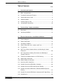
Table of Contents Table of Contents Seite 1. Introducing the System 5 1.1. DDC 1.2 Servo Drive ........................................................................6 1.2. Functional Performance Features ....................................................7 1.3. Command Interface Card .................................................................8 1.4 Software Module ..............................................................................9 1.5. Auxiliary Plug-In Cards .............
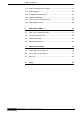
Table of Contents 3.17. Signal and Diagnostics Outputs .....................................................37 3.18. Signal Voltages ..............................................................................38 3.19. Reading Drive Parameters .............................................................39 3.20. Regenerated Power .......................................................................39 3.21. Fault Current Protective Device .....................................................40 3.22.
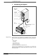
1. Intrroducing the System 1. Introducing the System DDC 1.2 drive controller configured configuration rating plate A1 A2 Software module viewing window plug-in modules mains Motor power cable interface to the machine controller Motor feedback cable AC servo motor MDD KBDKS1.8 Fig. 1.1: Digital AC drive with DDC drive controller Digital AC Drive Digital AC drives are microprocessor controlled, brushless, three-phrase drives which are highly dynamic and have precision servo-control features.
1.Introducing the System 1.1. DDC 1.2 Servo Drive IP65 is the protection category of a DDC 1.2. It can be installed directly at the feeder even under less favorable environmental and manufacturing conditions. This avoids long cables susceptible to faults. Basic unit A DC bus converter is built into the basic unit as well as the bleeder resistor for the energy generated during braking, a mains contactor for disconnecting the power and a power section for the control voltages.
1. Introducing the System 1.2.
1. Introducing the System 1.3. Command Interface Card Depending upon type, the command interface module is either the interface to the NC control unit or a positioning control unit with interfaces to the hand terminal or the NC control unit of the machine. The following command interface cards are available: • SERCOS interface, type: DSS 1.1, DSS 1.3 • ANALOG interface with incremental encoder emulator, type: DAE 1.1 • ANALOG interface with absolute encoder emulator, type: DAA 1.
1. Introducing the System 1.4 Software Module Type: DSM 2.1 Parmeters stored in the software module are used to tune the drive to the motor and the mechanics. Advantage when replacing unit The software module contains both the operating software and the parameters. This module ensures that when hardware is replaced, the previously entered parameters are not lost and can be carried over to the new hardware by simply plugging in the old software module.
1. Introducing the System 1.6 Configuration Rating Plate The configuration rating plate contains the type codes for: • the configured servo drive • the basic unit • the software module in slot U5 • the plug-in cards in slots U1 through U4 These type codes can be used to determine which components must be located in which slots. In the event of malfunctions, the information on the configuration rating plate can be used to obtain a corresponding unit or to configure a basic unit.
2. Technical Data/Ambient Conditions 2. Technical Data / Ambient Conditions DDC 1.2-N200A Designation DDC 1.2-N100A DDC 1.2-N050C 2.1. Data Sheet Power section 3x 220 V (+15%/-10%) or Input voltage U(N) (V) 3x 230 V (+10%/-15%) f(N) (Hz) 50 ...
2. Technical Data/Ambient Conditions 2.2. Operating Conditions Increased ambient temperatures The torque and power ratings listed in the selection documentation apply to an ambient temperature range of +5° to +45° C. Maximum permissible ambient temperature can equal up to +55° C. Otherwise, there is a drop in power as depicted in the following figure. Temperature factor [%] 100 80 60 40 20 ambient temperature ϑ [°C] 0 0 10 20 30 40 50 60 DGREDBELAST Fig. 2.
3. Electrical Connections - Installation Guidelines 3. : Electrical Connections Installation Guidelines The DDC 1.2 terminal diagram found in this document is a recommendation of the manufacturer of the unit. The circuit diagrams of the machine builder must be used for installation. • DOK-DIAX02-DDC01******-PRJ1-EN-E1,44 • 01.
3. Electrical Connections - Installation Guidelines 3.1. Terminal diagram ready-made cable IKS 374 INS 513 INK 209 TM+ E E 0VB G G K1 BR F F K1 free J D D C C B B A A frei X8 Digital Servo Feedback holding brake H U X5 TM- H Bb PTC INS 217 (INS 110 with DDC 1.2-N050C) MDD servo motor INS 290 UD Q1 3 x AC; 50...60 Hz L1 L2 L3 PE optional interface U4 Compact digital drive controller DDC 1.
3. Electrical Connections - Installation Guidelines 3.2. Power Connections Connection voltage Frequency The DDC 1.2 drives can be connected to three-phase mains rated at AC 220V (+ 15 % -10%) or AC 230V (+10 / -15%). 50 ... 60 Hz To operate the DDC 1.2 in residential and light industrial areas, it may be necessary to install an rf suppression filter in the mains supply line so that the limits for the emission of interference (radio interference suppression) are not exceeded.
3. Electrical Connections - Installation Guidelines 3.3. Grounding Conditions Grounded threephase systems With the help of an autotransformer, voltages can be adapted to three-phase mains witch is in reference to the ground (TN or TT mains). The DDC 1 can be directly connected to 3 x AC 220 V mains. Ungrounded threephase systems There is an increased danger in ungrounded mains (IT mains) that overvoltages will occur between the phases and the housing.
3. Electrical Connections - Installation Guidelines 3.4. Power Connection cross sections and Fuses The power connections of the DDC 1.2 can be protected with either power circuit breakers or slow-blo gL-type fuses. Fusing for three-phase connections The recommended fuse on the input side of the matching tansformer with 3 x AC 400 V mains. A power circuit breaker or slow-blow fuse is generally used on the input side of a matching transformer.
3. Electrical Connections - Installation Guidelines Cross section of the DDC 1 connecting cable Calculate the current in the connecting cable to determine cable cross section. threephase connection IL = IL SAN SA N 3 · 230V = current in connecting lead indicated in A = connected load indicated in VA The applicable guidelines must be followed when determining cable cross sections.
3. Electrical Connections - Installation Guidelines mains side (transformer side) device side 200 INS172 or INS108 with DDC1.2-N050C L1 L2 L3 PE 1 A 2 B 3 C yel/gn D SBDDC1 Fig. 3.4: Power supply cable for a DDC 1.2 3.5. Transformers Transformers for installation in control cabinets (IP 00) and transformers in housing with protection category IP 55 are available for adapting the mains voltage to the DDC 1 connecting voltage.
3. Electrical Connections - Installation Guidelines 3.6. DST Three-Phase Autotransformers for Mounting in Control Enclosures A B A B1 G vertical type for foot mounting Type DST.../S H E F D Example: rating plate C1 H E F D K C horizontal design for wall mounting Type DST.../L Block diagram: Type: Bj. DST 2,5/S/380/415/440-220 1993 Prim.: 380-400/415/440 V 440V U4 415V U3 380V 400V U2 V4 V3 V2 W4 W3 W2 Sec.
3. Electrical Connections - Installation Guidelines 3.7. DLT Three-Phase Isolating Transformers for Mounting in Control Enclosures A C1 B1 G1 B A Hø E F D G C Hø E F D vertical design for foot mounting Type DLT.../S Block diagram: Example: rating plate Type: Bj. DLT 2,5/S/380/415/440-220 1993 1U1, 1V1, 1W1 1U2, 1V2, 1W2 1U3, 1V3, 1W3 2U1, 2V1, 2W1 Prim.: 380-400/415/440 V Sec.: S 220-230V 2,5 kVA horizontal design for wall mounting Type DLT...
3. Electrical Connections - Installation Guidelines 3.8. Three-Phase Autotransformers in IP 55 Housing If transformers are to be mounted into housing, then this must be taken into consideration during planning. Due to the limit heat dissipation via the relatively small housing surface it is possible for standard transformers to reach unacceptably high temperature levels. Transformers of the type DST../G/ have been especially with a higher protection level for mounting into housing.
3. Electrical Connections - Installation Guidelines 3.9. Motor Power Connection Ready-made cables Ready-made cables are available for motor power connections. The motor power cable can be made available in individual parts upon request. Maximum cable length If INDRAMAT motor power cables are used, then maximum cable length is 75 meters. When operating the DDC 1.
3. Electrical Connections - Installation Guidelines Motor power cable capacity The following recommended cable types and cross sections are based on the current load capacity listed per EN 60 204 (VDE 0113) – E mode of installation. If other standards are required for the actual application, or if cables are routed to accomodate a different installation mode, then greater cable cross sections may be needed.
3. Electrical Connections - Installation Guidelines Recommended INDRAMAT Motor Power Cables Motor type MDD... DDC 1.2 connector on connector on motor INS 3) unit INS 3) INDRAMAT Cable for Motors Without Cooling motor phase current 21... 25... 41...
3. Electrical Connections - Installation Guidelines Recommended INDRAMAT Motor Power Cables Motor type MDD... DDC 1.
3. Electrical Connections - Installation Guidelines 3.10. Motor Feedback Connection Feedback Connection The feedback connections for motors with digital servo feedback (DSF) and resolver feedback (RSF) are built into cable leadthroughs inside the DDC 1, at terminal X4 (see section 4). Ready-made cables are also available. MDD motors with digital servo feedback can only be operated with DDC 1.2-.....-D...-XX and motors with resolver feedback only with DDC 1.2-.....-R...-XX units.
3. Electrical Connections - Installation Guidelines 3.11. Interface to NC Control Unit Ready-made cable Maximum cable length Interface X8 connects the DDC to the machine control unit. Ready-made cable, IKS083, is available for this purpose. Maximum cable length is 20 meters if ready-made cable IKS 083 is used. IKS 083/... INS 478 150 INK 271 (34 x 0.25 + 2 x 0.5) screwed connection part no.: 258 787 DDC X8 Ferrules 0.25mm2 1 WH (ws) 2 BN (bn) 0.25mm2 3 YE (ge) 0.25mm2 4 PK (rs) 0.
3. Electrical Connections - Installation Guidelines 3.12. Control Circuit of the DDC Mains Contactor The general operating method as suggested by INDRAMAT is to control the mains contactor and dynamic braking in the DDC. Selection of the control method and its effects will depend on the functions offered and the responses of the entire system. It is, therefore, the responsibility of the machine builder.
3. Electrical Connections - Installation Guidelines 3.13. Control Circuit in the DDC with Dynamic Braking Application This control circuit should be selected if a synchronous motor, e.g., MDD, is connected to the DDC. Features Dynamic braking always brakes synchronous motors to a standstill whether or not the drive electronics are operational. The DC bus is only short-circuited with a drive fault.
3. Electrical Connections - Installation Guidelines Control circuit of the DDC • with DC bus dynamic brake • with E-stop, regulated braking by the drive electronics PE L1 3 x AC (50-60Hz) L2 L3 F1 Q10 autotransformer DST 3 x AC 230V X7 A B C D DC 24V X8/15 X8/7 K1 Bb ZKS X8/8 S2 D NC X8/16 1 A X8/17 motor power connection S1 OFF B ZKS S4 C X8/18 machine NC control X5 K3 X7/A X8/19 ON X8/9 machine E-stop K3 S5 UD X8/10 X8/20 K3 2) & K4 K4 on impulse min.
3. Electrical Connections - Installation Guidelines 3.14. Control circuit of the DDC Mains Contactor Without Dynamic Braking Application • if an inductance motor is mounted to a DDC ( 2AD; 1MB; LAF; LAR ) • if uncontrolled coasting cannot damage the installation. Features The DC bus is not short-circuited. There can be no controlled braking of inductance drives if the DC bus is short-circuited. The drives are braked by the drive electronics at maximum torque for an E-stop or a power disconnect.
3. Electrical Connections - Installation Guidelines DDC control • without DC bus dynamic brake • regulated braking by the drive electronics with an E-stop PE L1 3 x AC (50-60Hz) L2 L3 F1 Q10 autotransformer DST 3 x AC 230V X7 A X8/15 B C D DC 24V K1 D X8/16 1 A X8/17 motor power connection S1 OFF B ZKS S4 C X8/18 X5 K3 X7/A machine NC control X8/19 K3 S5 ON X8/9 machine E-stop UD K4 K4 X8/10 on impulse min.
3. Electrical Connections - Installation Guidelines 3.15. Control Circuit of the DDC Mains Contactor with E-Stop Relays Application • if several E-stop switches are needed in larger installations or if, e.g., a safety door monitor is required or • if a synchronous motor (MDD) is connected to the DDC. Features Dynamic braking always brakes synchronous motors to a standstill whether or not the drives electronics are operational. The DC bus is only short-circuited if there is a drive fault.
3.
3. Electrical Connections - Installation Guidelines 3.16. Control Inputs DC bus dynamic brake Connector:X8/15-X8/16 Voltage: 24V DC Current consumption: 150 mA Input ZKS Operating state open closed Power OFF DC bus dynamic braking active Power ON DC bus dynamic braking not active The mains contactor on a DDC cannot be turned on unless ZKS input is closed. As an additional feature, when trouble occurs in the electronic system of the drive, the drive can be braked to a stop by opening the ZKS input.
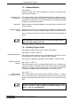
3. Electrical Connections - Installation Guidelines 3.17. Signal and Diagnostics Outputs Ready state Zero potential contact - Connector X8/7-X8/8 Maximum load: DC 24V/1A (do not attach higher voltages!) Operating state Relay power off Error ready Output Bb open open closed The Bb contact signals that the drive is ready for powering up. Internal interlocking devices will not permit the mains contactor in the DDC to be turned on until it is closed.
3. Electrical Connections - Installation Guidelines Mains contactor picked up Zero potential contact - Connector X8/3-X8/4 Maximum load: DC 24V/10A AC 230V/6A Operating state contactor dropped contactor picked up Output Power ON open closed It can be queried at output power ON whether the mains contactor has been switched on. The closed contact can be used as a condition for the drive enable signal.
3. Electrical Connections - Installation Guidelines 3.19. Reading Drive Parameters RS 232 Interface A VT 100 terminal or a PC with a VT 100 emulation program can be connected at connector X2 via an RS 232 interface to a DDC drive with analog command value input or with a single-axis positioning module. Drive parameters, such as amplilfication of velocity loops, can be output and optimized, if necessary, via these interfaces at the time of commissioning.
3. Electrical Connections - Installation Guidelines 3.21. Fault Current Protective Device Capacitive discharge currents always flow to earth in switch-mode drives. The extent of the discharge current is dependent upon: • the number of drives used, • the length of the motor power cable, • the motor type and • the ground conditions at the installation site.
4. Mounting the DDC 1.2 4. Mounting the DDC 1.2 The protection category of the DDC 1.2 is IP 65. It can be directly mounted to the feeding device. Long cable connections susceptible to interference are thus avoided. 7 25 9.5 7.5 4.1. DDC 1.2-N - dimensional data 470 interface to NC control of machine motor power conn. mains connection (22.5) interface to NC control of machine MBDDC 298 275 165 space for cable 140 7 (10) 40 shroud 635 517.5 500 shroud 13 220 Fig. 4.1: DDC 1.
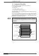
4. Mounting the DDC 1.2 4.2. Front View of DDC 1.
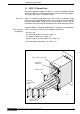
4. Mounting the DDC 1.2 4.3. Power Connections The protection category of the power terminal connectors (X7) of the DDC, the motor power terminal (X5), and the NC control unit interface (X8) is IP 65. The motor feedback cable and the connections for the optional plug-in cards are inserted in the DDC. These connections run through the cable leadthrough along the underside of the DDC. These must be carefully installed to maintain the IP 65 protection category.
4. Mounting the DDC 1.2 4.4. Minimum Clearances During installation, make sure that the air outlet is not obstructed and the bend radii of the cables are maintained. Minimum clearance equals allowance for power connectors plus bend radius, but not smaller than 300 mm. Bend radii of INDRAMAT cables Type Power core diameter (mm2) INK 250 1.5 11.4 ± 0.4 70 110 INK 202 2.5 17.6 +0.3/-0.5 120 200 INK 203 4.0 18.6 ± 0.5 120 270 INK 204 6.0 20 ± 0.5 120 300 INK 205 10.0 25.4 ± 0.
4. Mounting the DDC 1.2 The bleeder resistor in the DDC heats up during operation. Flammable materials or parts which could deform in the hot air stream, e.g., polyvinylchloride cable conduits, must maintain a minimum clearance of 300 mm to the air outlet. air outlet air outlet ≥ 300 Safety Clearances SYSTEMKONFIGURATION heatsink rB rB = bend radius ≥ bend radius bleeder FPLufteinaus Fig. 4.5: DDC - air inlet and outlet and position of bleeder resistor The DDC 1.
5. Order Informationen 5. Ordering Information 5.1. Type Codes for the DDC 1.2 Example: D D C 1 . 2 - N 0 5 0 A - D A 0 7 - 0 1 - FW 1. 1.1 Product name DDC . . . . . . . . = DDC 2. 2.1 Series 1 . . . . . . . . . . . . . . . . . . . .= 1 3. 3.1 Version 2........................=2 4. 4.1 4.2 Cooling type liquid. . . . . . . . . . . . . . . . . . . . . . . . . . air, natural convection . . . . . . . . 5. 5.1 5.2 5.3 Rated current 50 A . . . . . . . . . . . . . . . . . . . . . . . . . . . . .
5. Order Informationen 5.2. Accessories for Connections The following connectors and connector sets are available where ready-made cables are not used. Individual IP 65 connectors IP 65 connectors are used for the power connections of the DDC, motor power cable connections and the NC control unit connections. Name Connector type Power connection DDC 1.2-N050C DDC 1.2-N ... A INS 108/.. 1) INS 172/.. Motor power cable DDC 1.2-N050C DDC 1.2-N ... A INS 110/..2) INS 217/..
5. Order Informationen Individual connector sets If ready-made cable sets are only partially used, then the still required connectors for the plug-in modules can be ordered separately. Components Conn. strip Name of plug-in connector Part numer Text Comment DDS 2, DDS 3 drive controller X4 231 715 CONN. INS290 DKS 1 drive controller X4 231 715 CONN. INS290 DSS 1.1, DSS 1.3, DSS 2.1 SERCOS Interface X10 plug-in connector for feedback conn.
5. Order Informationen Components Conn. strip Name of plug-in connector Part numer Text DRF 1.1 analog signal interface X36 15 pin Dsub, male 231 715 CONN. INS290 DBS 1.1 Interbus S Interface X37 259 762 CONN. INS526 259 759 CONN. INS525 X25 9 pin Dsub, female 9 pin Dsub, male plug-in conn. for LWL cable X26 plug-in conn. for LWL cable 244 069 or 244 062 244 069 244 062 CONN. INS420 or CONN. INS425 CONN. INS420 or CONN. INS425 257 044 CONN. INS454 257 044 CONN.
5. Order Informationen 5.3. Item List Pos. Article Selection 1. Drive controller DDC 1.2-.....-....-.. Selection data 1.1 Firmware FW . . . Ask your local INDRAMATSales Rep. 1.2 Power connection Ready-made cable IK. .../.. or Connector INS ... and cable INK ... /.. 3.4 1.3 Motor power cable ready-made cable IK. .../.. or cable INK ... /.. ; motor side Connector INS ... and machine side Connector INS ... 3.9 1.4 Connection to NC control ready-made cable IKS 083/..
6.Index 6.
6. Index DLC single-axis postioning module 34 DLF 1.1 9 DLT Three-Phase Isolating Transformers Drive controller configuration 6 Drive enable 30, 34 DSF 27 DSM 2.1 9 DSS 1.1 8 DSS 1.3 8 DST ...
6.
6.
Indramat