
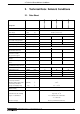
Technical data

14
• DOK-DIAX02-DDC01******-PRJ1-EN-E1,44 • 01.97
3. Electrical Connections - Installation Guidelines
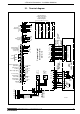
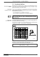
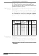
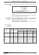
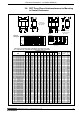
3.1. Terminal diagram
Fig. 3.1: Terminal diagram of DDC 1.2 servo drive
X7
power
infeed
control
voltage
infeed
APDDC11
Compact digital
drive controller
DDC 1.2
MDD
servo motor
M
3
X5
holding
brake
Digital Servo Feedback
TM+
TM-
BR
free
0VB
optional interface
module connections
as per relevant
terminal diagrams
PTC
U
INK 209
INS 513
ready-made
cable IKS
374
interface of command variables
U1
3 x AC; 50...60 Hz
Q1
K1
D
A
B
C
H
E
G
F
H
E
G
F
J
D
C
B
A
INS 217
(INS 110 with
DDC 1.2-N050C)
4
2
9
3
10
12
14
7
15
8
1
SDO
SDI
SCL
FS
X4
C +
C -
S +
S -
0VM
U
G
INS 290
optional interface
U2
optional interface
U3
optional interface
U4
DSM programming module
U5
analog
diagnostics
outputs
AK1
0V
M
AK2
0V
M
INS 172
(INS 108 with
DDC 1.2-N050C)
TxD
RxD
RTS
CTS
10
5
4
3
2
1
CTS
RTS
RxD
TxD
0V
M
RS 232
interface
X2
D
C
B
A
10
6
5
1
8
12
3
2
4
7
9
wh 1
2
gn
bn
pk
gr
bn 1
2
bk
red
bl
vio
4
3
2
1
X3
26
25
24
23
22
21
20
19
18
17
16
15
14
13
12
11
10
9
8
7
6
5
4
3
2
1
X8
acknowledge
Power OFF
acknowledge
Power ON
drive ready signal
power infeed
working
Bleeder temperature
prewarning
signal voltages
for measuring
and testing
purposes
0V
L
+15V
M
0V
M
-15V
M
+24V
L
INS 478
ZKS
OFF
ON
power
on
controls
K1
Bb
UD
BVW
K1
do not assign!
frei
L1
L2
L3
PE