
User Manual


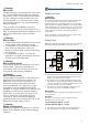
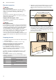
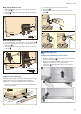
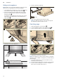
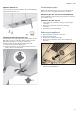
Table Of Contents
- [en] Instructions for installation and use
- Table of contents
- [en] Instructions for installation and use
- ( Important safety information
- Important safety information
- : Warning
- : Warning
- : Warning
- : Warning
- : Warning
- : Warning
- Causes of damage
- Saving energy
- Environmentally-friendly disposal
- Exhaust air mode
- Air recirculation
- Control panel
- Setting the fan
- Intensive setting
- Fan run-on time
- Lighting
- Cleaning agents
- Cleaning the metal mesh grease filters
- Removing metal grease filter
- Installing the metal mesh grease filter
- Malfunction table
- Replacing bulbs
- LED lights
- Accessories
- ( Important safety information
- Important safety information
- : Warning
- : Warning
- : Warning
- : Warning
- : Warning
- : Warning
- : Warning
- : Warning
- K General information
- Exhaust air mode
- Exhaust duct
- Electrical connection
- Preparing the units
- Appliance dimensions and safety clearances
- 1. Make the cut-out for the exhaust air pipe. To do this, make an opening in the top or back panel of the fitted unit with an additional recess for the power cord.
- 2. If the cabinet base is in place, remove it. Mark the fastening points on the inside of the cabinet and use a bradawl to make indentations where the holes are to be. To help you mark the fastening points, use the fastening piece provided.
- Body wall thickness: 16 mm
- Body wall thickness: 19 mm
- Appliance dimensions and safety clearances
- Preparing the appliance
- Sliding the appliance up into place
- Sliding out the appliance
- Note:
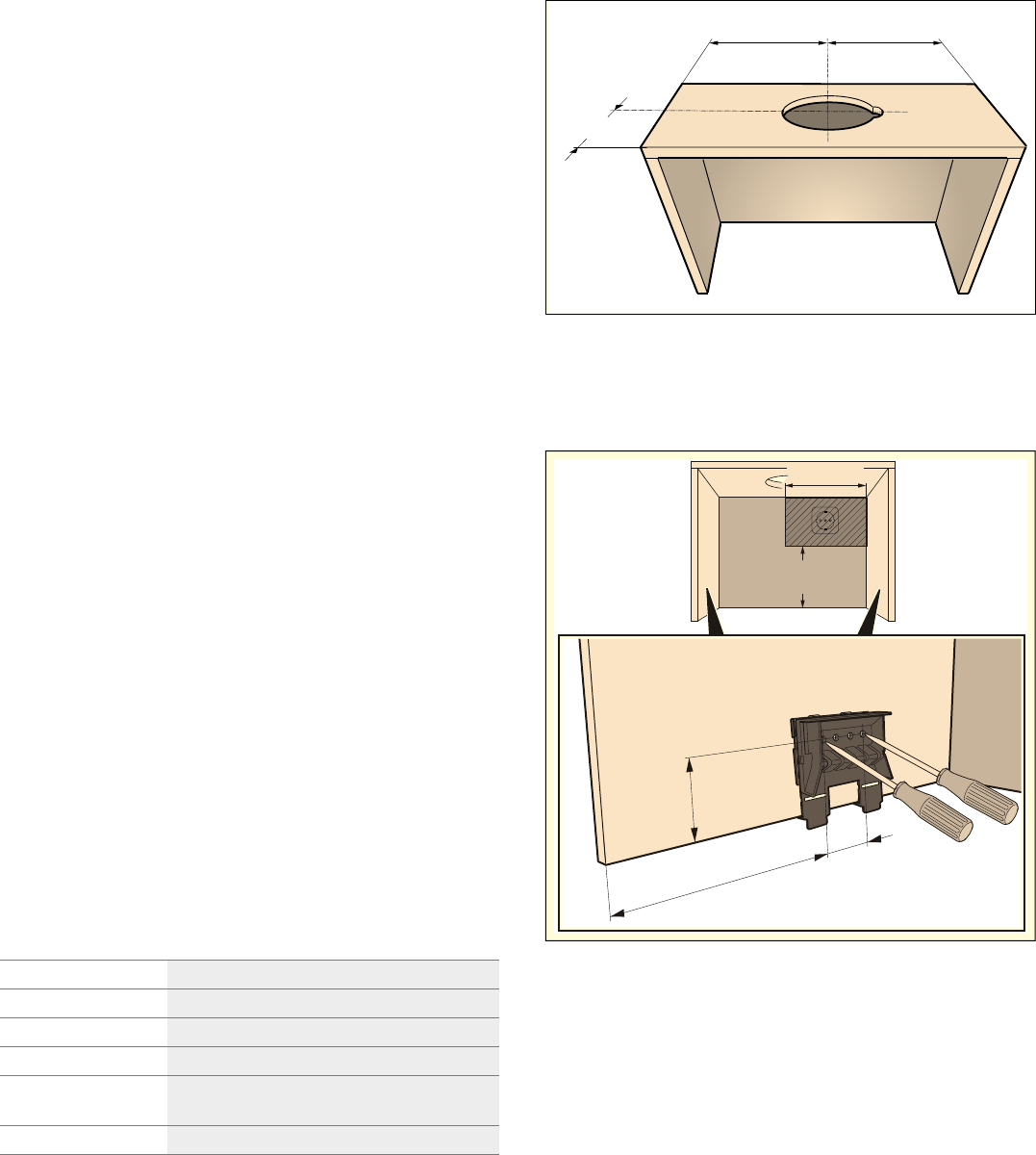
- 1. Use a flat-blade screwdriver to push in the fastening bolt, and turn it 90° until it locks into place. ¨
- 2. Push in the fastening bolt gently with your fingers, and turn it until it comes out of the housing along with the spring.©
- 3. Carefully remove the appliance.
- 4. Screw in the filler strip fully.
- 5. Push in the fastening bolt and turn it 90°.
- Note:
- Note:
- Final fitting stage
- Connecting the pipes
- Removing the appliance
en General information
12
Electrical connection
:Warning
Risk of electric shock!
Components inside the appliance may have sharp
edges. These may damage the connecting cable. Do
not kink or pinch the connecting cable during
installation.
The required connection data can be found on the
rating plate inside the appliance; to do this, remove the
metal mesh grease filter.
Length of the cable: approx. 1.30 m
This appliance complies with the EC interference
suppression regulations.
:Warning
Risk of electric shock!
It must always be possible to disconnect the appliance
from the electricity supply. The appliance must only be
connected to a protective contact socket that has been
correctly installed. If the plug is no longer accessible
once the appliance has been installed, or a fixed
connection is required, the installation must have an all-
pole isolating switch with a contact gap of at least
3 mm. Only an electrician may install the fixed
connection. We recommend installing a residual-current
circuit breaker (RCCB) in the appliance's power supply
circuit.
Preparing the units
■ The fitted unit must be level and have sufficient load-
bearing capacity.
■ The max. weight of the extractor hood is 18 kg.
Appliance dimensions and safety clearances
■ Observe the appliance's dimensions.
■ Comply with the safety clearances.
If the installation instructions for the gas cooking
appliances specify a different distance, the largest
distance must always be provided for.
The fitted unit must be heat-resistant up to 90 °C.The
fitted unit must still be sturdy after the cut-outs have
been made.
To install the extractor hood in a wall-hanging
cupboard, the extractor hood must be provided with the
following dimensions:
1. Make the cut-out for the exhaust air pipe. To do this,
make an opening in the top or back panel of the
fitted unit with an additional recess for the power
cord.
2. If the cabinet base is in place, remove it. Mark the
fastening points on the inside of the cabinet and use
a bradawl to make indentations where the holes are
to be. To help you mark the fastening points, use the
fastening piece provided.
Width 600 mm
Depth Min. 320 mm
Depth Min. 350 mm with lowering frame
Height Min. 420 mm
Height Min. 600 mm with CleanAir air recirculation
module
Wall thickness 16 mm or 19 mm
PP
PP
PLQ
PP