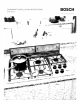
DOWNDRAFT INSTALLATION INSTRUCTIONS BOSCH DHD Models ¥Oij7_ I ,FF OUR INSp P,_TION .ii ,,'f_?t' ................................ """"" _,,'_F "'_ _ .... _" _, t,, @t ........ iiii....
en page 3-11 fr page 12-20 es p_.
z_ READ ALL INSTRUCTIONS READ Z_ SAFETY AND BEFORE SAVE THESE USING To reduced the risk of fire, electric shock, or injury to persons, observe the following: A. Installation work and electrical wiring must be done by authorized person(s) in accordance with all applicable codes and standards, including firerelated construction. B. Sufficient air is needed for proper combustion and exhausting of gases through the flue (chimney) of fuel burning equipment to prevent backdrafting.
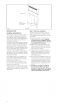
Downdraft Unit Blower/ Duct Transition Box (Not Included) Fig. 1 Strain Relief INTRODUCTION Step GENERAL Carefully follow the planning procedures listed below (See Figure 2). Sketches are NOT intended to be a replacement for careful planning. DESCRIPTION The complete downdraft system consists of the downdraft, a blower and a transition box if using an Inline or Remote Blower. A recirculation module is also available when ducting to the outside is not preferred or not possible. (See Fig. 1).
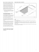
Dimension rain 1/4" 21/4" depends on Countertop ® ® | Be certain to avoid inteF ference with gas and electric supply to cooktop. 1/4" Shelving and drawer depths are dependent upon cooktop depth and setback. | 21/4" _i % ! 25 © _3 O_ Z3 Fig. 2 Investigate potential ductwork routes and choose the shortest possible route from the unit to an outside wall or to the roof via an inside wall and attic. For guidance, typical ducting installations are shown in figures 3 through 6.
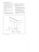
Figures Remote 3 through Blower Roof Mount ] hrough 6 are examples of possible Integral Installation DUCTWORK ducting GUIDE- ucting should vent directly outdoors (not into an attic, underneath the house, into the garage or into any enclosed space). A Recirculation Module is available when ducting to the outside is not Blower ] hrough INSTALLATION Wall Installation wall installation Blower ossible. eep duct runs as short and straight as ossible.
Step2:Prepare Countertop Cutout INSTALLATION Refer tothecooktop installation instructions fordimensions ofcook,top, countertop cutout, andcabinet requirements priorto making anycutouts. Cook,top depth and countertop back,-splash depth canvary greatly fromonetoanother. These variationsmaycause thefitofthedowndrafl and cook,top tobetight.Acountertop (front edge) witharaised lipand/or awideback,splash (back edge) maynotallow enough ftat countertop fora proper installation.
Step [] 5: Install Electrical Service Check` your local building codes for proper method of installation. In the U.S., if there are no applicable local codes, this unit should be installed in accordance with the National Electric Code ANSI/NFPA No. 70, Current Issue. (In Canada, installation must be in accordance with the CAN 1-B149.1 and .2-Installation Codes for Gas Burning Appliances and/or local codes). [] The appliance must be grounded.
Step7:MountIntegralBloweror OutletDuctTransition for Remote or IniineBlower Integral Blower (seeFigures 9and11for further detail): [] A.Attach blower infrontofround ex[] G.Place thecooktop incountertop opehaust outbtwith4-6(depending onconningwiththerearedgeofcooktop overfiguration) #8sheetmetal screws. lapping thefrontedgeofthevent.Make doesnotbind [] B.Feed cordfromblower through strain surerearedgeofcooktop against frontofsnorkek Follow themarelief. nufacturer's installation Instructions for [] C.
Remote orInlineBlower (see Figures 10 and11forfurther detail): [] A.Remove junction boxcover andconnectconduit with5wiresfromremote blower. Hook upwiresperWiring.Fig. 10. Replace junction boxcover. [] B.Attach DuctTransition Boxatmountinghales withsheetmetal screws. [] C.Feed remote blower pigtail through strain relief. [] D.Attach strain relbftodowndraft near junction box. [] E.Connect pigtail todowndrafl at6pin connector. [] RRunpigtail wires tojunction box. [] G.
WiringDiagram Step and [] LLJ z < [] 5_82888_ 0_ < co T I-- c_ °_ z i :> n'co I.L Ji i o _ i i s LU n- 2 LLJ _3 C3 __ Before performing this procedure, verify that all packing materials were removed from inside the snorkel and that the Plug the vent power cord into a proper electrical receptacle and ensure that the circuit is energized. [] B. Remove protective [] C. Turn the blower ON by selecting in turn each of the 3 speeds.
Z_ CONSIGNES LIRE TOUTES LES LIRE INSTRUCTIONS ET CONSERVER aces DE SECURITE AVANT CES D"UTILISER n6cessaires (standard) _. mesurer L'APPAREIL _.t6te Phillips d'aluminium INSTRUCTIONS pour conduits (configuration variant selon I'emplacement ; voir pages 7 _. 12 pour plus Z_ AVERTISSEMENT Pour reduire le risque d'incendie, de choc electrique ou de lesions corporelies, observer ce qui suit : A. L'installation et le cb.
Appareil de contre tirage / Soufflerie / BoTte de transition de conduit (non fournie) Fig. 1 Reducteur INTRODUCTION DESCRIPTION Gi_NERALE Le systeme de contre-tirage complet comprend le contre-tirage, une souffterie et une boTte de transition si I'on utilise une soufflerie en conduite ou _. distance. Un module de reoiroulation est egalement disponible Iorsque la raise en place de conduits vers I'exterieur n'est pas privilegi6e ou est impossible. (Voir fig. 1).
La dimension minx£- 1/4" depend du plan de travail ® S'assurer d'eviter une inteF f@ence avec le gaz et I'alimentation electrique _ la table de cuisson. 1/4" ® La profondeur de la tablette et du tiroir est dependante de la profondeur et du retrait de la table de cuisson. ! _1/_ j. 65/16"_ 10" E Verifier les chemins de conduit potentiels et choisir le plus court possible depuis I'appareil au mur ext@ieur ou au toit par un mur int@ieur et le grenier.
Les figures Soufflerie 3 & 6 sont des exemples de conduits Q'utilisation possibles de conduit rond en metal flexble peut se faire seulement si aucun autre raccord de conduit n'existe. Limiter b. distance Soufflene Installation sur le toit Installation par lemur int6gree Installation I'uti%ation par lemur _. de courtes Iongueurs et ne as ecraser les coins. es coudes poses les uns _. la suite des autres doivent 6tre evit6s. distance Q_.
_:tape 2 : pr6paration du plan Consulter de la d6coupe INSTALLATION AVEC TABLE DE CUISSON de travail la notice d'installation de la table de cuisson pour obtenir les dimensions de la table de cuisson, de la decoupe du plan de travail et les exigences de I'armoire avant d'effectuer une decoupe. La profondeur de la table de cuisson et la profondeur du dosseret du plan de travail peuvent varier considerablement I'une de I'autre.
[] L'appareil dolt 6tre mis b la terre. En cas de court-circuit, la mise a la terre reduit le risque de choc electrique en permettant au courant electrique de s'echapper par la terre Cet appareil est dote d'un cordon ayant un fil de mise _.
_:tape 7 int6gr6e conduit distance : installation de la soufflerie ou de la transition de de sortie pour la soufflerie & ou en conduite Soufflerie int_gr6e (voir figures 9 et 11 pour plus de details) : [] A. Fixer la soufflerie _.I'avant de la sortie d'echappement ronde avec 4 a 6 vis t61e n°8 (selon la configuration). [] B. Fairepasser le cordon de la souffletie a travers le reducteur de tension. [] C, Fixerle r6ducteur de tension avec les vis. [] D.
Soufflerie &distance ouenconduite (voir Rernarque :lasouffterie etlaboTte detransifigures 10et11pourplusdedetails) : tiondeconduit peuvent 8treinstallees avec deconduit _.gauche, verslebasou [] A.Retirer lecouvercle delabotte dejonction lasortie _.droite. Installer lasouffierie oulatransition etbrancher leconduit avec 5illsdepuis la soufflerie _distance. Brancher lesillsselon deconduit defagon _.cequelepanneau lediagramme dec_blage, figure 10Remet- d'acces puisse 8treenleve pourreparation.
Sch6ma dec&biage _:tape W W 3 w _ 3 ,< "< A IJJ cc d _o=###z- n < I-. © cc cc cc /"-\i J ....... de la Brancher le cordon d'allmentation de [] A. Ftlever Felevateur en position maximale en pressant la touche UP/DOWN une lois. Ne pas maintenir la touche enfoncee. Le moteur s'arr6te Iorsque I'elevateur atteint sa pleine hauteur. (Remarque : la souffierie ne fonctionne pas _. moins que Felevateur ne soit compl_tement eleve).
Z_ INSTRUCCIONES es necesarias DE SEGURIDAD (est&ndares) inta de medir LEA TODAS LAS INSTRUCCIONES LEA Y GUARDE ESTAS Z_ADVERTENCIA Para reducir el riesgo de fuego, descargas electricas o sufrir lesiones, observe Io siguiente: A. El trabajo de instalaciOn y la instalaci6n electrica deben ser realizados por (una) persona(s) autorizada(s) de acuerdo con todos los cOdigos y normas aplicables, incluidos los cOdigos de construcciOn con respecto a incendios. B.
Unidad de tiro descendente / Ventilad or/caja de transici6n del ducto (no incluidos) Prensacables Fig. 1 INTRODUCCION Paso DESCRIPCION Seguir los procedimientos de planeaci0n a continuaciOn cuidadosamente (Ver la Figura 2). Los dibujos NO reemplazan una planeaci0n cuidadosa. A. Determinar si se va a utilizar un ventilador remoto, en linea o integral. La instalaci6n de un ventilador remoto y en I{nea requiere 4 cables m_.s un cable de tierra desde el tiro descendente hasta el ventilador. B.
_-- Las dimensiones dependen de la cubierta ® I rain 1/4" I 21/4 " 1/4" AsegOrese de evitar la inteF ferencia con el suministro electrico la. ® y de gas a la parril- Las profundidades de estantes y cajones dependen de la profundidad y el retallo de la parrilla. Fig. 2 E Investigar posibles rutas de los ductos y escoger la ruta m_.s corta posible desde la unidad a una pared exterior o al techo a traves de una pared interior y atico.
Las Figuras 3 a 6 son ejemplos Ventilador montaje traves remoto InstalaciOn en el techo con InstalaciOn a de posibles Ventilador integral a traves de la pared Qolamente ductos se deben usar ductos redon- dos flexibles de metal cuando no existe ninguna otra conexiOn de ductos. Limitar el uso a longitudes cortas y no aplastar- InstalaciOn de la pared al hacerevitar esquinas. es deben los codos uno al otto.
Paso2:Preparar elrecorteenlacu- INSTALACION bierta Consultar lasinstrucciones deinstalaci6n delapardlla paraconocer lasdimensiones delaparrilla, delrecorte enlacubierta ylos requisitos delosgabinetes antes derealizar cualquier recorte. Laprofundidad delapardllaylaprofundidad delasalpicadura traseradelacubierta pueden vadar engran medida deunaaotra.Estas variaciones pueden hacer quequede muypocoespacioentre eltirodescendente ylapardlla.
[] El aparato debe estar conectado a tierra. En caso de un cortocircuito electrico, la conexi6n a tierra reduce el riesgo de una descarga electrica proporcionando un cable de escape para la corriente electrica. Esta aparato viene equipado con un cable con un hilo de conexi6n a tierra y un enchufe para conexi6n a tierra. Se debe enchufar en un tomacorriente correctamente instalado y puesto a tierra.
Paso7:Montarelventiladorintegral o latransici6ndelductodesalida paraelventiladorremotoo enIfnea Ventilador integral (verFiguras 9y11para [] G.Colocar laparrilla enlaabertura dela m_.s detalles): cubierta conelborde trasero delaparrillasuperpuesto alborde delantero dela [] A.Fijar elventilador enelfrente delasalida ventilaci6n. Asegurarse dequeelborde redonda deescape con4-6tornillos autortrasero delaparrilla notoque elfrente roscantes #8(segOn laconfiguraciOn). deltuboderespiraci6n. Seguir lasin[] B.
Ventilador remoto oenlinea(verFiguras 10y11param_.s detalles): [] A.Quitar latapadelacajadeconexiones Nota:Sepueden instalar elventilador yla yconectar elconducto con5cables del cajadetransiciOn delducto conlasalida ventilador remoto. Conectar loscables delductoalaizquierda, abajo oa laderecha.Instalar elventilador olatransiciOn del seg@n eldiagrama decableado, Fig.10. Volver acolocar latapadelacajade ductodetalmodo quesepuedan quitar los comexiomes. paneles deacceso pararealizar elservbio [] B.
Diagrama decableado Paso raci6n o cc _< $ x _ z o o_ _, 8C<_ z © 0 0 O_
Notes 30
Notas 31
YOURLIFE.OURINSPIRATION, 1901 Main Street, Suite 600 • Irvine • CA 92614 www.boschappliances.