
Installation guide


Figures 3 through 6 are examples of possible ducting
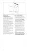
Remote Blower
Roof Mount Installation
] hrough wall installation
Remote
Blower
Fig. 3
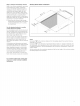
Blower
Integral Blower
] hrough Wall Installation
12" Min.
Ground
Fig. 4
Integral Blower
] hrough Wall Installation
,CONNECTION
Fig. 5
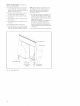
Ir/line Blower
] hrough Wall Installations
Wall Cap___ i
12" Min.
1__
Ground
Duct / I
'Transition
Box
ii,I
]lnline
Blower
Fig. 6
DUCTWORK INSTALLATION GUIDE-
ucting should vent directly outdoors
(not into an attic, underneath the house,
into the garage or into any enclosed
space). A Recirculation Module is availa-
ble when ducting to the outside is not
ossible.
eep duct runs as short and straight as
ossible.
uct fittings (elbows and transitions)
educe air flow efficiency.
ack to back elbows and "S" turns give
very poor delivery and are not recom-
mended.
_A short straight length of duct at the inlet
of the remote blower gives the best deli-
Or very'
ansition to duct from the integral blo-
wer or remote duct transition as close to
the downdrafl as is possible. In order of
preference, use
1st. 10" round duct
2nd. 8" round duct
3rd. 3-1/4" x 14" duct
4th. 7" round duct
5th. 3-1/4" x 10" duct
6th. 6" round duct
Ohe use of flexible metal round duct
should only be used when no other duct
fitting exists. Limit use to short lengths
_h d do not crush when making corners.
ck to back elbows should be avoided.
ere local codes permit, plastic pipe
(PVC-schedule 40 pipe or ABS pipe 7"
or 8" diameter) can be used in areas of
high ground moisture and in slab floors
o eliminate future rusting.
se only duct work constructed of mate-
rials that are acceptable by the applica-
ble codes. All duct should be 26 gauge
or heavier to minimize flex due to air
flow.
Ohe remote blowers require a 10" or 6"
diameter round duct (depending on
model) to match the inlet ring. A transiti-
n is necessary from other duct sizes.
se sheet metal screws as required to
support the duct weight, and seal all
ints with duct tape.
e certain that the duct work does not
interfere with floor joists or wall studs.
Qo not exhaust more than one vent into
single duct run.
old weather installations should have
an additional backdrafl damper installed
to minimize backward cold air flow and a
nonmetallic thermal break to minimize
conduction of outside temperatures as
part of the ductwork, The damper
should be on the cold air side of the
thermal break. The break should be as
close as possible to where the ducting
enters the heated portion of the house,
Iways use an appropriate roof or wall-
cap with damper. Laundry type wall caps
should never be used.