DHI 665 V / DHI 685 S de Gebrauchs- und Montageanleitung en Operating and installation instructions fr Mode d’emploi et notice de montage nl Gebruiksaanwijzing en montagevoorschrift it Istruzioni d’uso e per il montaggio es Instrucciones de uso y de montaje pt Instruções de serviçio e de montagem Internet: http://www.bosch-hausgeraete.de Bosch Info-Team: de Tel. 01 80/5 30 40 50 (E 0,12/Min.
de Seite 03 – 18 it pagina 67 – 082 en page 19 – 34 es página 83 – 098 fr page 35 – 50 pt página 99 – 114 nl pagina 51 – 66 Abb. 1 GAS GAZ KAASU GASS 2 ELEKTRO ELECTR. ELETT. EL.
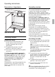
Operating instructions: Description of appliance Light / fan switches Filter drawer Operating modes Exhaust-air mode: ❑ The extractor-hood fan extracts the kitchen vapours and conveys them through the grease filter into the atmosphere. ❑ The grease filter absorbs the solid particles in the kitchen vapours. ❑ The kitchen is kept almost free of grease and odours. D If the extractor hood is operated in exhaust-air mode at the same time as a flue-type heater (e.g.
Before using for the first time Important notes: ❑ The Instructions for Use apply to several versions of this appliance. Accordingly, you may find descriptions of individual features that do not apply to your specific appliance. ❑ This extractor hood complies with all relevant safety regulations. Repairs should be carried out by qualified technicians only. Improper repairs may put the user at considerable risk.
Operating the extractor hood ! The most effective method of removing vapours produced during cooking is to: ❑ Switch the ventilator ON as soon as you begin cooking. ❑ Switch the ventilator OFF a few minutes after you have finished cooking. ❑ The fans in this appliance can be switched to the desired setting by hand (manual mode) or can be controlled fully automatically with the automatic function according to your requirements (automatic mode). Switching on manual mode: Press the L or + button.
Operating the extractor hood Switching on automatic mode: Intermittent ventilation Press the Ü button. ❑ The fan runs at least at Setting |. ❑ Used for ventilating the kitchen at hourly intervals at the lowest fan setting, round the clock. Switching on appliance: Press the button and insert the filter drawer. Fan settings: ❑ If required, the optimum fan setting is actuated automatically via a sensor. ❑ The automatic function operates at Settings | – ~. Intensive setting: 1.
Operating the extractor hood Switching off: Special functions There are 2 different methods of switching off the appliance whether in manual or automatic mode. Switching off directly: Press the L button. Switching on the light automatically, e.g. via a timer: ❑ Fan and light must be switched off. Switching on: Simultaneously press the a and L buttons. Important: All fan functions are switched off. Switching off appliance with fan run-on: Insert filter drawer all the way.
Filters and maintenance Grease filters: Metal-mesh filters are used to trap the grease particles in the cooking vapours. The filter mats are made from noncombustible metal. Caution: As the filter becomes more and more saturated with grease, there is an increased risk of fire and the function of the extractor hood may be impaired.
Filters and maintenance Activated carbon filter: For neutralizing odours in recirculating mode. Caution: As the filter becomes more and more saturated with grease, there is an increased risk of fire and the function of the extractor hood may be impaired. Important: Change the activated carbon filter promptly to prevent the risk of fire from the accumulation of heat when deep-fat frying or roasting. Inserting the filter: Warning: The halogen bulbs must be switched off and cool. 1.
Cleaning and care Replacing the light bulbs Isolate the extractor hood by pulling out the mains plug or switching off the fuse. ❑ When cleaning the grease filters, remove grease deposits from accessible parts of the housing. This prevents the risk of fire and ensures that the extractor hood continues operating at maximum efficiency. ❑ Clean the extractor hood with a hot soap solution or a mild window cleaner. ❑ Do not scrape off dried-on dirt but wipe off with a damp cloth.
Moving the operating unit Setting the saturation indicator You can move the operating unit from the middle of the filter drawer to the left or right side. The operating unit can also be fitted at the front in a handle moulding available as an optional accessory or in the enclosed handle moulding (see optional accessories on back page).
Installation Instructions: Important information ! Old appliances are not worthless rubbish. Valuable raw materials can be reclaimed by recycling old appliances. Before disposing of your old appliance, render it unusable. ! You received your new appliance in a protective shipping carton. All packaging materials are environmentally friendly and recyclable. Please contribute to a better environment by disposing of packaging materials in an environmentally-friendly manner.
Prior to installation Exhaust-air mode The exhaust air is discharged upwards through a ventilation shaft or directly through the outside wall into the open. D Exhaust air must not be discharged via a smoke or exhaust gas flue which is already in use or via a shaft which is used for ventilating rooms in which fireplaces are located. Discharge exhaust air in accordance with official and statutory regulations (e.g. national building regulations).
Before installation Optimum efficiency of the extractor hood: ❑ Short, smooth exhaust pipe. ❑ As few bends as possible. ❑ Pipe diameter as large as possible (ideally 150 mm dia.) and wide pipe bends. If long, rough exhaust-air pipes, many pipe bends or smaller pipe diameters are used, the air extraction rate will no longer be at an optimum level and there will be an increase in noise. ❑ Round pipes Short exhaust air pipe: inside diameter min. 120 mm, Longer exhaust air pipe: inside diameter min. 150 mm.
Preparing the wall cupboard This extractor hood is designed to be installed in a wall cupboard with the following dimensions: width: 600 mm depth: 293 to 350 mm height: min. 435 mm. If the cupboard is deeper than 293 mm, the extractor hood can be moved back, e.g. to put a spice rack in front of the extractor hood. II further To do this, place the template O back. 1. Mark two attachment points on both the right and left inside faces of the cupboard and make holes with a bradawl.
Fitting into wall cupboard ! Check door alignment and readjust if necessary. 1. Remove grease filter (see Operating instructions). 2. Lift the extractor hood into the cupboard from below until both fixing lugs have locked firmly into position. 4. If required, shorten the wall cover to the required dimension (e.g. saw off). Attach the wall cover with the enclosed clips. Screw the wall cover to the wall cupboard. 3. Tighten the two fixing screws with a screwdriver (cordless). 5.
Fitting into wall cupboard ❑ If the extractor hood is to be installed further back in the cupboard, the stops for the filter drawer can be moved forwards. ❑ To do this, undo the screws, move the stops and retighten the screws. Moving the operating unit: See Operating instructions. Attaching the handle moulding: A handle moulding must be attached to the filter drawer.
Electrical connection WARNING: THIS APPLIANCE MUST BE EARTHED IMPORTANT: Fitting a Different Plug: The wires in the power cord are colourcoded as follows: Green and Yellow – Earth Blue – Neutral Brown – Live If you fit your own plug, the colours of these wires may not correspond with the identifying marks on the plug terminals. Proceed as follows: 1. Connect the green and yellow (Earth) wire to the terminal in the plug marked ‘E’ or with the symbol ( ), or coloured green or green and yellow. 2.
2 1 3 DHZ 4505 4 5 3x 434229 Aluminium: DHZ 4675 Metall: DHZ 4655 Aluminium: DHZ 4670 Metall: DHZ 4650 Absenkrahmen Lowering frame Du cadre d’abaissement Befestigingsframe Dei telai per l’abbassamento Bastidor para bajar DHZ 4600
Robert Bosch Hausgeräte GmbH 5750 203 747 Printed in Germany 0704 Es.