DinionXFD_Nv1_0.
DinionXFD_Nv1_0.book Page 2 Friday, January 7, 2005 10:56 AM DinionXF | Installation Manual EN | 2 SAFETY PRECAUTIONS Danger The lightning flash with arrowhead symbol, within an equilateral triangle, is intended to alert the user to the presence of uninsulated “dangerous voltage” within the product's enclosure that may be of sufficient magnitude to constitute a risk to persons.
DinionXFD_Nv1_0.book Page 3 Friday, January 7, 2005 10:56 AM DinionXF | Installation Manual EN | 3 9. Do not defeat the safety purpose of the polarized or grounding-type plug. A polarized plug has two blades with one wider than the other. A grounding type plug has two blades and a third grounding prong. Both the wide blade and the third prong are provided for your safety. If the supplied plug does not fit into your outlet, consult an electrician for advice. 10.
DinionXFD_Nv1_0.book Page 4 Friday, January 7, 2005 10:56 AM DinionXF | Installation Manual EN | 4 FCC Information This equipment has been tested and found to comply with the limits for a Class B digital device, pursuant to part 15 of the FCC Rules. These limits are designed to provide reasonable protection against harmful interference in a residential installation.
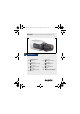
DinionXFD_Nv1_0.book Page 5 Friday, January 7, 2005 10:56 AM DinionXF | Installation Manual EN | 5 Introduction The DinionXF Day/Night is a high-performance smart surveillance color camera. It incorporates 15-bit digital signal processing for outstanding picture performance under all lighting conditions. The DinionXF Day/Night is easy to install and ready to use, and offers the best solution for demanding scene conditions.
DinionXFD_Nv1_0.book Page 6 Friday, January 7, 2005 10:56 AM DinionXF | Installation Manual EN | 6 Unpacking Unpack carefully and handle the equipment with care. The packaging contains: • DinionXF Day/Night camera • CS to C lens mount adapter • CCD protection cap • Spare lens connector (male) • These instructions Note If equipment appears to have been damaged during shipment, repack it in the original packaging and notify the shipping agent or supplier. Bosch Security Systems | 2004-01 | V1.
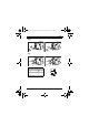
DinionXFD_Nv1_0.book Page 7 Friday, January 7, 2005 10:56 AM DinionXF | Installation Manual EN | 7 Connections Power Low voltage versions VIDEO VIDEO 10mm High voltage versions DC 12V AC 24V SVHS SVHS SYNC SYNC ALARM ALARM For low voltage cameras: • push in the tabs to open the quick-connectors (these connections are not polarity sensitive). • use AWG16 to 22 stranded wire or AWG16 to 26 solid wire; cut back 10mm (0.4") of insulation.
DinionXFD_Nv1_0.book Page 8 Friday, January 7, 2005 10:56 AM DinionXF | Installation Manual EN | 8 Sync VIDEO VIDEO DC 12V AC 24V SVHS SYNC SVHS SYNC ALARM ALARM Y/C VIDEO VIDEO DC 12V AC 24V SVHS SVHS SYNC SYNC ALARM Pin Y/C socket 1 GND Y 2 GND C 3 Y 4 C Bosch Security Systems | 2004-01 | V1.
DinionXFD_Nv1_0.book Page 9 Friday, January 7, 2005 10:56 AM DinionXF | Installation Manual EN | 9 Alarm connector Pin Alarm socket 1 Alarm in Ground 2 Alarm in 3 Relay out contact 1 4 Relay out contact 2 Alarm Pin 1 • • • • • • Pin 4 Max. wire diameter AWG 22-28 for both stranded and solid Default relay position n.o. (normally open), no alarm Alarm output relay switching capability: Max voltage 30VAC or +40VDC. Max 0.5 A continuous, 10VA.
DinionXFD_Nv1_0.book Page 10 Friday, January 7, 2005 10:56 AM DinionXF | Installation Manual EN | 10 Bosch Bosch Pin Video iris lens 1 Supply (11.5V ±0.5, 50mA max.) DC iris lens Damp - 2 Not used Damp + 3 Video signal 1Vpp 1kOhm Drive + 4 Ground Drive - Note If a short circuit is detected on the lens connector, the on-screen display (OSD) failure message LENS SHORT CIRCUIT is shown. The lens circuit is automatically disabled to avoid internal damage.
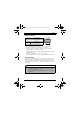
DinionXFD_Nv1_0.book Page 11 Friday, January 7, 2005 10:56 AM DinionXF | Installation Manual EN | 11 Back focus adjustment To optimize picture sharpness in both bright and low-level lighting, adjust the back focus. Use the camera's unique Lens Wizard (see Advanced Setup). This ensures that the object of interest always remains in focus even when focusing at the maximum lens opening.
DinionXFD_Nv1_0.book Page 12 Friday, January 7, 2005 10:56 AM DinionXF | Installation Manual EN | 12 Mounting the camera The camera can be mounted from the top or bottom. The bottom mounting is isolated from ground. With outdoor scenes, a DC-iris lens is recommended. Caution Do not point the camera/lens into direct sunlight. Day/Night switching The DinionXF Day/Night Camera is equipped with a motorized IR filter. The IR filter can be removed in low-light or IR illuminated applications.
DinionXFD_Nv1_0.book Page 13 Friday, January 7, 2005 10:56 AM DinionXF | Installation Manual EN | 13 Advanced Set-up The DinionXF Day/Night normally provides an optimal picture without the need for further adjustments. However, advanced set-up options are available for getting the best results from the camera under special circumstances. There are two main menus; a Mode menu and an Installer menu. The camera has three pre-programmed operating modes that can be selected in the Mode menu.
DinionXFD_Nv1_0.book Page 14 Friday, January 7, 2005 10:56 AM DinionXF | Installation Manual EN | 14 Menu Structure Mode Mode ALC Enhance Color BLC VMD Mode ID Defaults Exit ALC ALC level Shut/Gain Peak / average ALC speed Shut/Gain Shutter Defshut Sens up Gain Max.
DinionXFD_Nv1_0.book Page 15 Friday, January 7, 2005 10:56 AM DinionXF | Installation Manual EN | 15 Installer Lens Wizard I/O Sync Camera ID Defaults Exit Lens wizard Lens type Detected Set back focus Set level I/O Sync input Communication Cable comp Comp level Alarm Sync Sync Detected sync V phase H phase Subphase Camera ID Camera ID ID position MAC address All Defaults Confirm Bosch Security Systems | 2004-01 | V1.
DinionXFD_Nv1_0.book Page 16 Friday, January 7, 2005 10:56 AM DinionXF | Installation Manual EN | 16 Hints for menu navigation How to use the 5 keys Up key Menu/select key Right key Left key Lock Down key • • Press the menu/select key to access the menus or to move to the next or previous menu. Press the menu/select key for approximately 1.5 seconds to open the Installer menu. • • Use the up or down keys to scroll up or down through a menu.
DinionXFD_Nv1_0.
DinionXFD_Nv1_0.
DinionXFD_Nv1_0.book Page 19 Friday, January 7, 2005 10:56 AM DinionXF | Installation Manual EN | 19 Day/Night submenu Function Selection Description DAY/NIGHT COLOR, MONO, AUTO • In COLOR mode the camera will always give a color image. • In MONO mode the IR filter is removed, giving full IR sensitivity in a monochrome image. • In AUTO mode the camera switches the filter depending on the scene illumination level.
DinionXFD_Nv1_0.book Page 20 Friday, January 7, 2005 10:56 AM DinionXF | Installation Manual EN | 20 Color submenu Function Selection Description WHITE BALANCE ATW, MANUAL, AWB HOLD • ATW: Auto tracking white balance allows the camera to constantly adjust for optimal color reproduction. • AWB HOLD: Puts the ATW on hold and saves the color settings.
DinionXFD_Nv1_0.book Page 21 Friday, January 7, 2005 10:56 AM DinionXF | Installation Manual EN | 21 menu, the current area is displayed with the upper left corner flashing. The flashing corner of the image can be moved with the Up, Down, Left, Right arrow keys. Pressing the Select key moves the flashing cursor to the opposite corner, which can now be moved. Pressing Select again freezes the area and exits the area menu.
DinionXFD_Nv1_0.
DinionXFD_Nv1_0.book Page 23 Friday, January 7, 2005 10:56 AM DinionXF | Installation Manual EN | 23 Adjustment procedure Manual-iris Lens: 1. Unlock the back focus locking button. 2. Adjust the lens to the maximum lens opening. 3. Turn the back focus adjustment as required. 4. Lock the back focus locking button. Adjustment procedure Video-iris Lens: 1. Unlock the back focus locking button. 2. Access the Lens Wizard menu. 3. SET BACK FOCUS NOW is highlighted in the menu. 4.
DinionXFD_Nv1_0.book Page 24 Friday, January 7, 2005 10:56 AM DinionXF | Installation Manual EN | 24 Install I/O --> Alarm submenu Function Selection Description ACTIVE NONE, HIGH, LOW Selects active_HIGH or active_LOW for the alarm input connector. Select NONE to disable alarm switching. ACTION NONE, MONO, Selects the operating mode of the camera upon MODE1, MODE2, switching the alarm input.
DinionXFD_Nv1_0.book Page 25 Friday, January 7, 2005 10:56 AM DinionXF | Installation Manual EN | 25 Install ID submenu Function Selection CAMERA ID ID POS Description Enter a 16 character camera name string. Use LEFT/RIGHT to change position in the string, use UP/DOWN to select the character. Use SELECT to exit the string edit screen. OFF, TOP, BOT EXIT Select TOP to display the camera ID in the upper left corner; select BOT for the lower left corner.
DinionXFD_Nv1_0.book Page 26 Friday, January 7, 2005 10:56 AM DinionXF | Installation Manual EN | 26 Technical specification 1/2" CCD versions Type number LTC 0620/11 LTC 0620/21 LTC 0620/51 LTC 0620/61 Standard PAL NTSC PAL NTSC Active pixels 752x582 768x492 752x582 768x492 Rated supply voltage 24 VAC or 12 VDC 12-28 VAC (50/60 Hz) 11-36 VDC Min illumination < 0.18 lux < 0.
DinionXFD_Nv1_0.
DinionXFD_Nv1_0.
DinionXFD_Nv1_0.book Page 1 Friday, January 7, 2005 10:56 AM Bosch Sicherheitssysteme GmbH Ludwig-Bölkow-Allee 85521 Ottobrunn Germany www.bosch-sicherheitssysteme.de © 2004 Bosch Security Systems B.V. Subject to change. Printed in Portugal. 3122 165 23061 Bosch Security Systems B.V. P.O. Box 80002 5600 JB Eindhoven The Netherlands www.boschsecuritysystems.