DIVAR IP 2000 DIP-2040-00N, DIP-2042-2HD, DIP-2042-4HD en Installation Manual
DIVAR IP 2000 Table of Contents | en 3 Table of contents 1 Safety precautions 4 1.1 General safety precautions 4 1.2 Electrical safety precautions 5 1.3 ESD precautions 6 1.4 Operating precautions 6 2 System overview 7 2.1 Chassis features 7 2.2 Chassis components 7 2.2.1 Chassis 7 2.2.2 Backplane 7 2.2.3 Power supply 7 2.3 Device views 8 2.3.1 LED description - front panel 2.3.2 LAN port LED description - rear panel 10 3 Chassis setup and maintenance 11 3.
en | Safety precautions DIVAR IP 2000 Safety precautions 1 Observe the safety precautions in this chapter. General safety precautions 1.1 Follow these rules to ensure general safety: – Keep the area around the system clean and free of clutter. – Place the chassis top cover and any system components that have been removed away from the system or on a table so that they won't accidentally be stepped on.
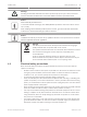
DIVAR IP 2000 Safety precautions | en 5 Warning! ! Handling of lead solder materials used in this product may expose you to lead, a chemical known to the State of California to cause birth defects and other reproductive harm. Notice! Electrostatically sensitive device: To avoid electrostatic discharges, the CMOS/MOSFET protection measures must be carried out correctly.
en | Safety precautions – DIVAR IP 2000 Mainboard replaceable soldered-in fuses: Self-resetting PTC (Positive Temperature Coefficient) fuses on the mainboard must be replaced by trained service technicians only. The new fuse must be the same or equivalent as the one replaced. Contact technical support for details and support. Caution! Mainboard Battery: There is a danger of explosion if the onboard battery is installed upside ! down, which will reverse its polarities.
DIVAR IP 2000 2 System overview | en 7 System overview The DIVAR IP 2000 system is an affordable, easy to use all-in-one recording and management solution for network surveillance systems of up to 16 channels. All channels are pre-licensed. Running the full Bosch recording solution including the Video Streaming Gateway to integrate 3rd party cameras, DIVAR IP 2000 is an intelligent IP storage device that provides both, a professional video recording solution and ease of operation.
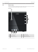
en | System overview 2.3 DIVAR IP 2000 Device views There are several LEDs on the front and rear of the chassis. The LEDs show the over-all status of the system and the activity and health of specific components. Front view: 1 6 2 2013.
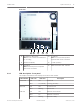
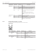
DIVAR IP 2000 System overview | en 9 Rear view: 1 1 2 3 4 1x eSATA for data export 5 6 4 2x USB 3.0 Note: Do not connect hard disk drives Note: Do not use these ports for for recording. keyboard and mouse connection. 2 1x Ethernet (RJ45) 5 1x VGA (monitor) 3 2x USB 2.0 6 Mains connection 100 - 240 VAC Note: Use these ports for keyboard and mouse connection. 2.3.1 LED description - front panel This chapter describes the LED displays on the front of the chassis.
en | System overview DIVAR IP 2000 LED indicator System LED LED color LED state Description N/A Off Power off Blue On (default) System has booted in normal operation. Blue Blinking System is booting or shutting down Red On Critical event occurred, such as degraded RAID volume. Bosch also provides the API and then application program is able to control this status. Individual hard disk LED N/A Off (default) Hard drive not present. Blue On Hard drive present.
DIVAR IP 2000 3 Chassis setup and maintenance | en 11 Chassis setup and maintenance This chapter covers the steps required to install components and perform maintenance on the chassis. Caution! ! Review the warnings and precautions listed in the manual before setting up or servicing this chassis. See also: Safety precautions, page 4 3.1 Removing hard drive trays The drives are mounted in drive carriers to simplify their installation and removal from the chassis.
en | System setup - first steps 4 DIVAR IP 2000 System setup - first steps The following installation directive provides information on Installation and Configuration. DIVAR IP systems are based on Windows Storage Server 2008 R2 operating system. This chapter is valid for DIVAR IP models that come with pre-installed hard drives. Empty units start into the DOM recovery menu on first start. See also: – Recovering the unit, page 23 4.
DIVAR IP 2000 System setup - first steps | en 8. 13 After entering the password, a message is displayed that you must change the password before logging on the first time. To confirm, click OK. 9. Change the password. A series of scripts perform important setup tasks. This can take several minutes. Do not turn off the computer. A page is displayed where you can perform initial Windows configuration tasks.
en | System setup - first steps DIVAR IP 2000 Welcome page 4 Click Next > to start the configuration. Notice! If VRM is not available on the computer or the license check fails, a corresponding error message is displayed. You cannot continue working with Configuration Wizard. 2013.
System setup - first steps | en DIVAR IP 2000 15 Passwords page This page allows you to specify a password to protect the devices from unauthorized access. 4 Enter the respective password, confirm the password, then click Next >. Bosch Sicherheitssysteme GmbH Installation Manual 2013.
en | System setup - first steps DIVAR IP 2000 Recorder page This page displays recorder information. 4 2013.09 | V2 | DOC Click Next > to continue.
System setup - first steps | en DIVAR IP 2000 17 Device Selection page This page displays all network devices that are added to the system. Clicking Update starts the scan process again. 4 Click Next > to continue. Bosch Sicherheitssysteme GmbH Installation Manual 2013.
en | System setup - first steps DIVAR IP 2000 Network page This page allows you to configure the network settings of connected devices. 4 2013.09 | V2 | DOC Click Next > to continue.
System setup - first steps | en DIVAR IP 2000 19 Date and Time page This page allows you to synchronize the device time with the computer time or a SNTP time server. 4 Click Next > to continue. Bosch Sicherheitssysteme GmbH Installation Manual 2013.
en | System setup - first steps DIVAR IP 2000 Video Quality page This page allows you to define the image quality for live-viewing and to set the maximum bandwidth. 4 2013.09 | V2 | DOC Click Next > to continue.
System setup - first steps | en DIVAR IP 2000 21 Recording page This page allows you to define the recording profiles. 4 Click Next > to continue. Bosch Sicherheitssysteme GmbH Installation Manual 2013.
en | System setup - first steps DIVAR IP 2000 Summary page This page displays a summary of all wizard settings. 4 2013.09 | V2 | DOC Click Apply to activate the configuration.
DIVAR IP 2000 5 Recovering the unit | en 23 Recovering the unit Following procedure describes how to restore the factory default image. To restore the unit to factory default image 1. Start the unit and press F7 during the BIOS power-on-self-test. The Recovery menu is displayed. Notice! Make sure that a VGA monitor, a keyboard and a mouse are connected to the unit. 2.
en | Additional documentation and client software 6 DIVAR IP 2000 Additional documentation and client software Documentation for Bosch Security System products can be found as follows: 4 www.boschsecurity.com > select your region and your country > select Product Catalog > start a search for your product > select the product in the search results to show the existing documents. And on the following network share: 4 2013.
Bosch Sicherheitssysteme GmbH Robert-Bosch-Ring 5 85630 Grasbrunn Germany www.boschsecurity.