
Installation Manual


© 2011 Bosch Security Systems, Inc.
130 Perinton Parkway, Fairport, NY 14450-9199 USA
www.boschsecurity.com
F01U252565-01
Installation Guide
9/11
DS150i/DS151
i
Page 2 of
4
3.2 EMF (Voltage) Spike-Protected Relay
Pins 6 through 8 (wire colors gray, green, and orange) comprise the EMF
spike-protected relay. Refer to Figure 3.
Use this relay when connecting inductive loads to the detector. This relay
protects the detector from inductive loads that might deliver damaging
EMF spikes.
3.3 Non-EMF (Voltage) Spike-Protected Relay
Pins 3 through 5 (wire colors yellow, violet, and blue) comprise the non-
EMF spike-protected relay. Refer to Figure 3.
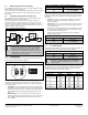
This relay is best used for non-inductive loads. When connecting an
inductive load that is not spike-protected, such as a magnetic door lock, to
the detector, use either a bridge rectifier (such as a KBL01) or a diode
(such as a 1N4007). Failure to use a bridge rectifier/diode may reduce the
lifetime of the relay. Refer to Figure 5.
Figure 5: Wiring the Bridge Rectifier
S
S
DS150i
Relay Contact
(non-spike protected)
Inductive
Load
KBL01
Bridge Rectifier
Power
Supply
+
+
-
Power
Supply
Inductive
Load
1N4007
Diode
+
-
OR
DS150i
Relay Contact
(non-spike protected)
UL 1034 listed magnetic locks typically are already EMF
spike-protected, and therefore do not require the bridge
rectifier or diode as shown in Figure 5. Adding a bridge
rectifier/diode to an EMF spike-protected device can cause
unwanted delays in response. Refer to the magnetic lock’s
documentation for more information.
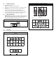
4.0 Configuration
Use the on-board DIP switches to configure the operation of the detector.
Refer to Figure 6 for proper switch positioning.
Figure 6: DIP Switch ON/OFF Positions
ON DIP
ON
ON
ON
OFF
4.1 Resettable/Non-resettable Timer Selection
DIP Switch 1 determines if the relay resets at the end of latch time, or if
latch time is extended by additional motion. Refer to Table 1 and Figure 6
for more information.
Resettable: The relay activates when the detector first sees motion.
Any additional motion restarts the latch timer so the relay deactivates
only when the detector no longer sees motion and the latch time has
expired. Hint: This setting works best when bypassing a 24-hour
contact.
Non-resettable: The relay activates when the detector first sees
motion. It deactivates when the latch time ends, even if motion is still
present. Hint: This setting works best when used with an access
control system.
Table 1: Resettable/Non-resettable DIP Switch Settings
Switch 1 Function
OFF Non-resettable
ON Resettable (Default)
4.2 Relay Mode
DIP Switch 2 selects the relay mode. This allows you to select a fail safe
by default, or a fail secure mode. Refer to Table 2 and Figure 6 for more
information.
Fail Safe: In the event of a power loss, the REX detector releases
the device connected to it (for example, magnetic door lock or
electric door strike).
Fail Secure: In the event of a power loss, the REX detector does not
release the device connected to it (for example, magnetic door lock
or electric door strike).
In Fail Secure mode, the REX detector shall be installed in a manner
that does not impair the intended operation of panic hardware used
in conjunction with the REX detector.
Failure Secure mode must be authorized by the local Authority
Having Jurisdiction (AHJ).
Table 2: Relay Mode DIP Switch Settings
Switch 2 Function
OFF Fail Secure
ON Fail Safe (Default)
Refer to Figure 4 relay wiring options.
4.3 Led Enable/Disable
DIP Switch 3 selects whether the on-board LED is enabled or disabled. If
enabled, the LED operates normally when motion is detected.
Table 3: LED Enable/Disable DIP Switch Settings
Switch 3 Function
OFF Disabled
ON Enabled (Default)
When LED is enabled, it will flash on and off when first
powered up. Once the flashing LED stops, the REX is
ready to be used.
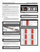
4.4 Latch Time
DIP Switches 4, 5, and 6 set the relay latch time. Latch time is adjustable
from 0.5 sec to 64 sec. It indicates the amount of time the relay can
remain active after the detector first sees motion.
Table 4: Latch Time DIP Switch Settings
Time (sec) Switch 4 Switch 5 Switch 6
0.5 (Default) OFF OFF OFF
1 OFF OFF ON
2 OFF ON OFF
4 OFF ON ON
8 ON OFF OFF
16 ON OFF ON
32 ON ON OFF
64 ON ON ON