DS7200V2-EXP Expert Programming Guide EN Control Panel
DS7200V2-EXP | Expert Programming Guide | Contents EN | 2 Contents 1. Introduction ...............................................................................................................................................................4 1.1 Documentation Conventions.................................................................................................................................4 1.1.1 Type Styles Used...................................................................................
DS7200V2-EXP | Expert Programming Guide | Figures EN | 3 Figures Figure 1: Routing Destination Phone Number Configured for Basic Pager................................................................
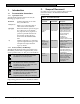
DS7200V2-EXP | Expert Programming Guide | 1. 1. Introduction 1.1 Documentation Conventions 1.1.1 Type Styles Used To help identify important items in the text, the following type styles are used: Bold text Indicates important text or terms that you should note. Italicized text Refers you to a drawing, table, or other section of this document. [9][8][7][6] Bracketed numbers represent keypad keys. When next to one another, they represent the key sequence to press for a particular function.
DS7200V2-EXP | Expert Programming Guide | 3. How to Program 3.1.2 3. How to Program 3.1 Keypad Programming 3.1.1 Installer Mode/Installer Menu A text keypad such as the DS7447E or DS7447V2 LCD Keypad can be used for keypad programming. The DS7445i and DS7445V2 LED Keypads cannot be used for keypad programming. Installer Programming Mode: Installer Programming Mode is the control panel’s default programming mode.
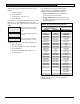
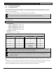
DS7200V2-EXP | Expert Programming Guide | 3. Follow these steps to edit the data digit entry for an address: How to Program EN | 6 1. Enter the address. Certain addresses are skipped during keypad programming: Reserved addresses and Expert addresses. Table 2 identifies these addresses. 2. Press the [#] key. • 3. Enter the new value (0 to 15). Reserved Addresses: These addresses are reserved for future development. 4. Press the [*] key.
DS7200V2-EXP | Expert Programming Guide | 3. 3.1.4 Text Entry Addresses All text entry addresses (System Text, Area Text and Location Text) require the use of a special textprogramming mode. In this mode, the keypad keys display different characters depending on the number of times the keys are pressed. See Table 3. A character’s order in the character selection sequence indicates the number of key presses necessary to produce the character. For example, pressing the [2] key four times produces “a.
DS7200V2-EXP | Expert Programming Guide | 4. 4. Control Panel Programming EN | 8 Control Panel Programming The contents of this section are organized as in Remote Programming Software (RPS). This section covers all of the available programming parameters. The programming section in the DS7200V2 Installer’s Guide (P/N: 4998153893) covers the programming parameters only available when the control panel is in the Installer Programming Mode.
DS7200V2-EXP | Expert Programming Guide | 4. 4.2 Panel Wide Parameters 4.2.1 Routing Destinations Control Panel Programming EN | 9 The control panel has two routing destinations for the routing of reports. The control panel routes by zone and report group to the destinations. For example, you can send alarm reports for one zone to Destination 1 and for another zone to Destination 2. You can program two phone numbers (or IP addresses) for each destination.
DS7200V2-EXP | Expert Programming Guide | 4. Control Panel Programming EN | 10 Format for Destination 1 (2) • Address: − − Format for Destination 1: 0064 Format for Destination 2: 0130 • Default: 2 (Contact ID) • Selections: 2 to 4, 7, 11 − − − − − 2 = Contact ID 3 = SIA 300 4 = Basic Pager 7 = Personal Dialing Format 11 = SIA 300 with Text Blocks This parameter selects the reporting format. All reports for this destination are sent in the format chosen here.
DS7200V2-EXP | Expert Programming Guide | 4.
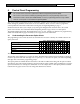
DS7200V2-EXP | Expert Programming Guide | 4. Control Panel Programming EN | 12 For example, if Data Digit Selection “5” is entered, the following report tone is transmitted (“-“ equals 1 beep): -- -. There is a 1-second pause between the transmission of the first digit and the second digit. The second digit is followed by a 3-second pause.
DS7200V2-EXP | Expert Programming Guide | 4. Control Panel Programming EN | 13 The End Page Field follows the Format Field. The digits you enter in this field are sent after the paging message. For many paging services, a ‘#’ indicates the end of the paging message. The End Page Field ends with a Field Terminator (0). You must enter the pauses required for the paging service in the Digits to Dial Field before the Digits to Dial field terminator.
DS7200V2-EXP | Expert Programming Guide | 4. 4.2.3 Control Panel Programming EN | 14 Phone, Auto-Forward, and RPS Configuration Integral Voice Verification Module • Address: 0065 • Default: 0 • Selections: − − 0 = Disable Voice Verification 1 to 15 = Enable the Voice Verification Module and identify which output is the Voice Request output in Area 1 This parameter enables the voice verification module. Program one of the first 15 outputs as Output Function Type 2|10 “Voice Request.
DS7200V2-EXP | Expert Programming Guide | 4. Control Panel Programming EN | 15 DTMF/Pulse Dialing • Address: 0132 • Default: 0 (DTMF) • Selections: − − 0 = DTMF 1 = Pulse This parameter selects the control panel dialing format (DTMF or Pulse). This format is used for all dialing attempts.
DS7200V2-EXP | Expert Programming Guide | 4. Control Panel Programming EN | 16 Remote Programming Call Back Number • Address: 0181 to 0212 • Default: All zeroes (0) • Selections: See Table 4 on page 9 The control panel dials this phone number (or IP address) to begin a RPS remote programming session. See Network Communication on page 129 for complete network communication programming instructions. Firmware revision 2.10 or greater is required for network communication.
DS7200V2-EXP | Expert Programming Guide | 4.
DS7200V2-EXP | Expert Programming Guide | 4.
DS7200V2-EXP | Expert Programming Guide | 4. 4.2.4 Control Panel Programming EN | 19 Global Reporting Options These parameters configure the reporting for all areas, all zones, and all users.
DS7200V2-EXP | Expert Programming Guide | 4. • Control Panel Programming EN | 20 Burg Alarm After Two Failed Attempts: If this option is enabled, a steady alarm output sounds after two failed attempts to transmit a burglary alarm report from any zone when its area is armed. Alarm output is provided even if the zone is not programmed for alarm output. Program Bell Time to at least 3 min. when using this option.
DS7200V2-EXP | Expert Programming Guide | 4.
DS7200V2-EXP | Expert Programming Guide | 4.
DS7200V2-EXP | Expert Programming Guide | 4.
DS7200V2-EXP | Expert Programming Guide | 4.
DS7200V2-EXP | Expert Programming Guide | 4.
DS7200V2-EXP | Expert Programming Guide | 4. Control Panel Programming EN | 26 Auto On Alert Time • Address: 0233 • Default: 3 (15 min.) • Selections: 0 to 15 (Time = Selection x 5 min.) Multiply the value entered in this parameter by five (5) min. to determine the duration of the Auto On Alert. The alert sounds before the Auto On Sked to warn users to exit or extend ([#][5][1]) the auto arming. At the Auto On time, the control panel starts exit delay.
DS7200V2-EXP | Expert Programming Guide | 4.
DS7200V2-EXP | Expert Programming Guide | 4.
DS7200V2-EXP | Expert Programming Guide | 4. Control Panel Programming EN | 29 • Test Battery: If enabled, this option makes the “battery test” part of the system test. The battery test causes the system to run on battery power only for four min. If the battery voltage falls below 12.1 V during the fourmin. test, or if the battery is missing, the system restores AC power and displays a system trouble at all keypads.
DS7200V2-EXP | Expert Programming Guide | 4.
DS7200V2-EXP | Expert Programming Guide | 4.
DS7200V2-EXP | Expert Programming Guide | 4. Control Panel Programming EN | 32 Automatic Test {137} Report Interval • Address: 0254 • Default: 3 (7 Days) • Selections: − − − − − 0 = No Automatic Test 1=1H 2 = 1 Day 3 = 7 Days 4 = 28 Days Enter zero (0) to disable Automatic Test {137} reporting. The one-hour interval is incremented on the minute.
DS7200V2-EXP | Expert Programming Guide | 4. 4.2.
DS7200V2-EXP | Expert Programming Guide | 4. Control Panel Programming EN | 34 Daylight Saving Clock Advance Time • Address: 0238, 0239 • Default: 0,2 (02:00 AM) • Selections: 0 to 22 Addresses 0238 and 0239 select the hour that the clock is advanced. Address 0238 holds the tens digit of the hour and Address 0239 holds the ones digit of the hour. When the local time of the control panel matches the value entered in Addresses 0238 and 0239, an hour is added to the time.
DS7200V2-EXP | Expert Programming Guide | 4.
DS7200V2-EXP | Expert Programming Guide | 4.
DS7200V2-EXP | Expert Programming Guide | 4. 4.2.
DS7200V2-EXP | Expert Programming Guide | 4.
DS7200V2-EXP | Expert Programming Guide | 4.
DS7200V2-EXP | Expert Programming Guide | 4.
DS7200V2-EXP | Expert Programming Guide | 4. Control Panel Programming EN | 41 Entry Delay Time 1 (2) • Address: • Entry Delay Time 1: 0264, 0265 • Entry Delay Time 2: 0266, 0267 • Default: − − • Entry Delay Time 1: 1,14 (30 sec) Entry Delay Time 2: 7,8 (120 sec) Selections: 0,0 to 15,15 (0 to 255 sec) Entry Delay is the time the system allows the user to turn the system off before an alarm initiates. If the user fails to turn off the system before Entry Delay expires, an alarm event occurs.
DS7200V2-EXP | Expert Programming Guide | 4. Control Panel Programming EN | 42 Perimeter Only Mode Delay Time • Address: 0268, 0269 • Default: 0,0 (use assigned Entry Delay) • Selections: 0,0 to 15,15 (0 to 255 sec) Making an entry in the Perimeter Only Mode Delay Time parameter creates an Entry Delay time that only applies when the system is armed Perimeter Only.
DS7200V2-EXP | Expert Programming Guide | 4. Control Panel Programming EN | 43 Exit Delay Time 1 (2) • Address: − − • Default: − − • Exit Delay Time 1: 0270, 0271 Exit Delay Time 2: 0272, 0273 Exit Delay Time 1: 3,12 (60 sec) Exit Delay Time 2: 7,8 (120 sec) Selections: 0,0 to 15,14 (0 to 254 sec) Exit Delay is the time the system allows users to exit the premises. Users must leave the premises before Exit Delay expires. The control panel provides two Exit Delays.
DS7200V2-EXP | Expert Programming Guide | 4.
DS7200V2-EXP | Expert Programming Guide | 4.
DS7200V2-EXP | Expert Programming Guide | 4. Control Panel Programming EN | 46 Panel Arming Options • Address: 3411 • Default: 0 • Selections: 0 to 7 Panel Arming Options No Panel Arming Options Enable Bad Set Operation Panel is Disarmed during Exit Delay Start Exit Delay with Faulted Zones Reserved 0 1 Enter This Data Digit to Select Options 2 3 4 5 6 7 8 9 10 11 12 13 14 15 • • • • • • • • • • • • • This is a global parameter.
DS7200V2-EXP | Expert Programming Guide | 4. Control Panel Programming EN | 47 Verified Alarm Timer • Address: 3412, 3413 • Default: 1,14 (30 min.) • Selections: − − 0,0 (Disabled) 1,14 (30 min.) to 3,12 (60 min.) This parameter sets the time for the Verified Alarm Timer. The amount of time entered in this parameter defines the window of time in which two independent alarms must occur for the control panel to declare a verified alarm.
DS7200V2-EXP | Expert Programming Guide | 4. 4.3 Control Panel Programming EN | 48 Area Wide Parameters The parameters in this section configure the control panel’s areas. Each area has 16 characters of programmable text for an area name and 16 characters of programmable area idle text, which appear on the LCD Keypad display. The DS7240V2 supports up to four areas. The DS7220V2 supports up to two areas. All control panel text is programmed from the text keypad in a special text-programming mode.
DS7200V2-EXP | Expert Programming Guide | 4.
DS7200V2-EXP | Expert Programming Guide | 4. Control Panel Programming EN | 50 Lock Area # Reporting • Address: − − − − Area 1: 0297 Area 2: 0319 Area 3 (DS7240V2 only): 0341 Area 4 (DS7240V2 only): 0363 • Default: 0 (Lock Area Disabled) • Selections: − − − 0 = Lock Area Disabled 1 = Lock Area Reports to Routing Destination 1 2 = Lock Area Reports to Routing Destination 2 This parameter locks area reporting to either Routing Destination 1 or Routing Destination 2.
DS7200V2-EXP | Expert Programming Guide | 4. Control Panel Programming EN | 51 Area Idle Text • Address: − − − − Area 1 Idle Text: 1426-1457 Area 2 Idle Text: 1490-1521 Area 3 Idle Text (DS7240V2 only): 1554-1585 Area 4 Idle Text (DS7240V2 only): 1618-1649 • Default: Not Ready • Selections: See Key/Character selection chart All control panel text is programmed from the text keypad in a special text-programming mode. See Text Entry Addresses on page 7 for text programming instructions.
DS7200V2-EXP | Expert Programming Guide | 4. 4.4 User Interface 4.4.1 Authority Level Configuration Control Panel Programming EN | 52 The Authority Level determines which functions are available to system users. Each user is assigned an authority level. Use the parameters in this section to configure each of the four authority levels available in the control panel.
DS7200V2-EXP | Expert Programming Guide | 4.
DS7200V2-EXP | Expert Programming Guide | 4.
DS7200V2-EXP | Expert Programming Guide | 4.
DS7200V2-EXP | Expert Programming Guide | 4.
DS7200V2-EXP | Expert Programming Guide | 4.
DS7200V2-EXP | Expert Programming Guide | 4.
DS7200V2-EXP | Expert Programming Guide | 4.
DS7200V2-EXP | Expert Programming Guide | 4.
DS7200V2-EXP | Expert Programming Guide | 4.
DS7200V2-EXP | Expert Programming Guide | 4.
DS7200V2-EXP | Expert Programming Guide | 4. Control Panel Programming EN | 63 Installer PIN • Address: 0383 to 0389 • Default: 9876543 • Selections: 0 to 9 Do not use digits 10-15 when creating the Installer PIN or User PIN. Entering these digits makes the PIN unusable and locks the installer out of the control panel. The Installer PIN length is the same as all other system PINs (see PIN Length on page 61). The default PIN length is 4 digits, which makes the Installer PIN 4 digits in length.
DS7200V2-EXP | Expert Programming Guide | 4. 4.4.3 Control Panel Programming EN | 64 Users The control panel reserves the following User IDs for automated functions: 251 (control panel generated); 252 (Sked operation); 253 (remote telephone communication); 254 (RPS communication); 255 (keyswitch operation or any local operation that does not require a PIN entry, such as Quick Arming). See Table 10 for User parameter addresses and defaults. Defaults for User 1 are shown in (bold).
DS7200V2-EXP | Expert Programming Guide | 4. Control Panel Programming EN | 65 PIN, User # • Address: See Table 10 on page 64 • Default: − − • User 1: 1, 2, 3, 4, 5, 6, 7 Users 2-32: 15, 15, 15, 15, 15, 15, 15 Selections: 0 to 9 Enter a PIN for each user in the PIN parameter. The PIN length parameter determines the number of digits in the PINs. The default PIN length is 4 digits, which makes all User PINs four digits in length.
DS7200V2-EXP | Expert Programming Guide | 4.
DS7200V2-EXP | Expert Programming Guide | 4. 4.4.4 Control Panel Programming EN | 67 Keypads Wired Keypads 1 to 8 are fixed at Data Bus Addresses 1 to 8. See “Keypad Addressing” in the DS7200V2 Installer’s Guide (P/N: 4998153893). All keypads (and other Data Bus devices) are fully supervised. Supervision reports, such as missing and tamper, follow the System Status Report routing.
DS7200V2-EXP | Expert Programming Guide | 4. • Control Panel Programming EN | 68 Don’t Show Zone Status on Keypads: If the “Don’t Show Zone Status on Keypads” option is not enabled in the Keypad # Options parameter, the text keypad displays “OK for All On” or “OK for Perimeter Only” across the second line. This indicates that all zones are normal and the system is ready to arm All On or Perimeter Only.
DS7200V2-EXP | Expert Programming Guide | 4.
DS7200V2-EXP | Expert Programming Guide | 4.
DS7200V2-EXP | Expert Programming Guide | 4. 4.4.5 Control Panel Programming EN | 71 ABC Keys and Duress Parameters The following parameters configure the keypad’s ABC keys and the Duress function for all keypads and areas. Each key has 16 characters of programmable text that is displayed when the key is activated (press twice to activate).
DS7200V2-EXP | Expert Programming Guide | 4. Control Panel Programming EN | 72 Alarm Output Option for ABC Keys • Address: 0700 • Default: 0 • Selections: 0 to 7 Alarm Output Options No Alarm Output for ABC Keys Alarm Output for [A] Key Alarm Output for [B] Key Alarm Output for [C] Key Reserved 0 1 Enter This Data Digit to Select Options 2 3 4 5 6 7 8 9 10 11 12 13 14 15 • • • • • • • • • • • • • This parameter assigns an alarm output option to the ABC keys.
DS7200V2-EXP | Expert Programming Guide | 4.
DS7200V2-EXP | Expert Programming Guide | 4. Control Panel Programming EN | 74 Guard Code Options • Address: 0705 • Default: 0 (No Guard Code Options) • Selections: − − 0 = No Guard Code Options 1 = User 28 is a Guard Code User 28 can be programmed as a Guard Code. The Guard Code only works in the areas to which User 28 is assigned. The authority level assigned to the Guard Code (User 28) dictates which keypad functions the guard can use.
DS7200V2-EXP | Expert Programming Guide | 4. 4.4.6 Control Panel Programming EN | 75 RF Keypads The control panel supports up to four RF keypads. Each keypad has two programming parameters. RF keypads report conditions such as low battery and tamper by transmitter number. You must exit control panel programming in order to enter RF ID codes. Add RF ID codes after you complete your programming session. See “Adding RF ID Codes” in DS7200V2 Installer’s Guide (P/N: 4998153893) for complete instructions.
DS7200V2-EXP | Expert Programming Guide | 4. Control Panel Programming EN | 76 RF Keypad # Area • Address: − − − − RF Keypad 1: 2931 RF Keypad 2: 2933 RF Keypad 3: 2935 RF Keypad 4: 2937 • Default: 0 (Disabled) • Selections: − − − − − 0 = Disabled (No Area Assigned) 1 = Assign RF Keypad to Area 1 2 = Assign RF Keypad to Area 2 3 = Assign RF Keypad to Area 3 (DS7240V2 only) 4 = Assign RF Keypad to Area 4 (DS7240V2 only) To enable an RF keypad, assign it to an area.
DS7200V2-EXP | Expert Programming Guide | 4.
DS7200V2-EXP | Expert Programming Guide | 4. 4.4.8 Control Panel Programming EN | 78 RF Keyfobs RF keyfobs (two- and four-button keychain keypads) are managed internally by the control panel. Keyfobs are assigned to PINs (users) by entering IDs. No other programming parameters are required. Keyfobs generally follow the authority level and area assignment for the PIN they are assigned to. RF keyfobs report low battery conditions using the user number (1 to 32).
DS7200V2-EXP | Expert Programming Guide | 4.
DS7200V2-EXP | Expert Programming Guide | 4. 4.5 Zone Parameters 4.5.1 Location Configuration Control Panel Programming EN | 80 The DS7240V2 supports Locations 1 to 40. The DS7220V2 supports Locations 1 to 24. Locations become zones by configuring the following parameters: Device, Zone Function, Area, and Zone Number. All four of these parameters must be configured for each location being used in the system. See Table 13 for location parameter addresses and defaults (defaults are shown in bold).
DS7200V2-EXP | Expert Programming Guide | 4. Control Panel Programming EN | 81 Table 13: Location Configuration Parameters (continued) Location Parameters These columns show the addresses and defaults for each of the four location parameters. These parameters configure each location. Shaded cells only apply to the DS7240V2.
DS7200V2-EXP | Expert Programming Guide | 4. Control Panel Programming EN | 82 Zone Doubling Programming Zone doubling requires 3.65 k Ω and 2.2 k Ω EOL resistors as shown in Table 13. If zone doubling is not used, see On-board Location EOL Resistor Value on page 103, and DX2010 Configuration Options on page 127, for on- and off-board zone EOL resistor configuration. For proper zone doubled wiring, see the DS7200V2 Installer’s Guide (P/N: 4998153893).
DS7200V2-EXP | Expert Programming Guide | 4.
DS7200V2-EXP | Expert Programming Guide | 4. Control Panel Programming EN | 84 Location ##, Zone Function • Address: See Table 13 on page 80 • Default: See Table 13 on page 80 • Selections: 0 to 15 (see Table 15 for Default Zone Function Types) The zone function determines how the system responds to changes on the sensor loop assigned to the location. There are two general categories of zones: 24-hour and Controlled. • 24-hour Zone: 24-hour zones are always on and cannot be turned off by the user.
DS7200V2-EXP | Expert Programming Guide | 4. Control Panel Programming EN | 85 Location ##, Area • Address: See Table 13 on page 80 • Default: 1 (Area 1) • Selections: − − − − − 0 = No Area Assigned (Disabled) 1 = Assign Location ## to Area 1 2 = Assign Location ## to Area 2 3 = Assign Location ## to Area 3 (DS7240V2 only) 4 = Assign Location ## to Area 4 (DS7240V2 only) This parameter assigns an area to a location. Each location can only be assigned to one area.
DS7200V2-EXP | Expert Programming Guide | 4.
DS7200V2-EXP | Expert Programming Guide | 4. Control Panel Programming EN | 87 RF Transmitters and Zone States With the exception of the point transmitter, all RF transmitters show only two electrical zone states (Normal and Faulted). The RF3401E Point Transmitter can monitor both a reed switch (magnet) and a supervised sensor loop.
DS7200V2-EXP | Expert Programming Guide | 4. 4.5.2 Control Panel Programming EN | 88 Zone Function Configuration The control panel can monitor any combination of up to 40 sensor loops and/or RF transmitters. Each sensor loop or transmitter is assigned to a location. Each location is assigned to one of 15 Zone Functions so that the control panel knows how to respond to sensor loop or transmitter changes.
DS7200V2-EXP | Expert Programming Guide | 4. Control Panel Programming EN | 89 Zone Wiring Configuration The operation and configuration of the zone function depends on the method of zone wiring. A zone is a “Single EOL resistor” zone if the zone is supervised with one end of line resistor. Table 18 defines configuration options for single EOL resistor zones.
DS7200V2-EXP | Expert Programming Guide | 4. Control Panel Programming EN | 90 Zone Function Type, Zone Function • Address: See Table 17 on page 88 • Default: See Table 17 on page 88 • Selections: 0 to 15 (see Table 20) See Table 20 for a description of each zone function type and the events and reports associated with that Zone Function type, when the zone is wired using one of the following configurations: single EOL resistor, tamperwired, zone-doubled, or no EOL resistor.
DS7200V2-EXP | Expert Programming Guide | 4. Control Panel Programming EN | 91 Table 20: Zone Function Type Options (continued) Zone Function Type 4 5 6 7 8 9 10 24-hr Tamper 24-hr Emergency 24-hour Visible Panic 24-hr Invisible Panic 24-hr Burglary Reserved Controlled Keyswitch Wiring Configuration Description Single EOL Resistor Can create a Tamper Alarm or a Tamper Trouble based on option programming.
DS7200V2-EXP | Expert Programming Guide | 4. Control Panel Programming EN | 92 Table 20: Zone Function Type Options (continued) Zone Function Type 11 12 Controlled Entry/Exit Delay 1 Controlled Entry/Exit Delay 2 Wiring Configuration Description Events/Reports Single EOL Resistor When control panel is On, short or open starts Entry Delay 1 if no Trouble Option. Follows Entry Delay 1 or 2. Follows Exit Delay.
DS7200V2-EXP | Expert Programming Guide | 4. Control Panel Programming EN | 93 Table 20: Zone Function Type Options (continued) Zone Function Type 14 15 Controlled Instant 24-hr Door Wiring Configuration Description Single EOL Resistor When armed, short or open causes alarm response. Short or open during Entry/Exit Delay creates an instant alarm, which terminates the Exit Delay period (see Panel Arming Options on page 46).
DS7200V2-EXP | Expert Programming Guide | 4.
DS7200V2-EXP | Expert Programming Guide | 4.
DS7200V2-EXP | Expert Programming Guide | 4. • Control Panel Programming EN | 96 Alarm Event Abort (Non-Fire Zones Only): If enabled, this option assigns the Abort Window to a zone function. See Alarm Event Abort Window on page 106 to learn how to set the Alarm Event Abort Window. − If a user acknowledges a non-fire alarm zone event by entering their PIN before the Alarm Event Abort Window expires, the following events occur: − The alarm event is aborted.
DS7200V2-EXP | Expert Programming Guide | 4. Control Panel Programming EN | 97 Options 1 for Zone Function Type 3 (24-hr Control Input) • Address: See Table 17 on page 88 • Default: See Table 17 on page 88 • Selections: 1 to 4, 9 to 12 The 24-hour Control Input zone function type uses the following parameter option chart.
DS7200V2-EXP | Expert Programming Guide | 4. Control Panel Programming EN | 98 Options 1 for Zone Function Type 4 (24-Hour Tamper) • Address: See Table 17 on page 88 • Default: See Table 17 on page 88 • Selections: 0, 2, 8, 10 The 24-hour Tamper zone function type uses the following parameter option chart.
DS7200V2-EXP | Expert Programming Guide | 4.
DS7200V2-EXP | Expert Programming Guide | 4.
DS7200V2-EXP | Expert Programming Guide | 4.
DS7200V2-EXP | Expert Programming Guide | 4.
DS7200V2-EXP | Expert Programming Guide | 4. 4.5.3 Control Panel Programming EN | 103 Global Zone Configuration On-board Location EOL Resistor Value • Address: 1026 • Default: 5 (Tamper-wired loops, single tamper-wired sensors) • Selections: − − − − − − − 0 = No EOL Resistor 1 = 1 k EOL Resistor 2 = 2.2 k EOL Resistor 3 = 3.65 k EOL Resistor 4 = Zone Doubled, 2.2 k & 3.
DS7200V2-EXP | Expert Programming Guide | 4.
DS7200V2-EXP | Expert Programming Guide | 4. Control Panel Programming EN | 105 Swinger Count for Zone Reports • Address: 1030 • Default: 3 • Selections: − − 0 (Swinger disabled) 1 to 15 This parameter sets the swinger count for zone alarm, trouble, and restoral reports. Swinger shut down for the dialer is a global function that affects all zones. Swinger Shunt {33} reports are sent for Swinger Shunt of zones.
DS7200V2-EXP | Expert Programming Guide | 4. Control Panel Programming EN | 106 Alarm Event Abort Window • Address: 1034 • Default: 3 (45 sec) • Selections: − − − 0 to 1 = 15 sec 2 = 30 sec 3 to 15 = 45 sec This parameter sets the length of time that a user has to enter a valid PIN and cancel an alarm before an alarm report is sent. If a user acknowledges a non-fire alarm event by entering their PIN before the Alarm Event Abort Window expires, the following events occur: 1.
DS7200V2-EXP | Expert Programming Guide | 4. 4.6 Output Parameters 4.6.1 Global Output Configuration Control Panel Programming EN | 107 The DS7240V2 supports up to 20 outputs: four on-board Programmable Outputs (PO 1 to PO 4), and up to 16 off-board using two DX3010 Output Expanders. The DS7220V2 supports up to 12 outputs: four on-board Programmable Outputs (PO 1 to PO 4), and up to 8 off-board using one DX3010 Output Expander.
DS7200V2-EXP | Expert Programming Guide | 4. Control Panel Programming EN | 108 Bell Time • Address: 1040 • Default: 6 (min.) • Selections: 0-15 (1-minute increments) Bell Time determines how long, 0 to 15 min., the Alarm Output, Fire Alarm Output, Silent Alarm Output, and Bell Time functions remain activated when triggered by an alarm event.
DS7200V2-EXP | Expert Programming Guide | 4.
DS7200V2-EXP | Expert Programming Guide | 4. 4.6.2 Control Panel Programming EN | 110 Output Configuration The DS7240V2 supports up to 20 outputs: four on-board Programmable Outputs (PO 1 to PO 4), and up to 16 off-board using two DX3010 Output Expanders. The DS7220V2 supports up to 12 outputs: four on-board Programmable Outputs (PO 1 to PO 4), and up to 8 off-board using one DX3010 Output Expander. PO 2 can be configured as a supervised speaker output (8 Ω, 10 watt).
DS7200V2-EXP | Expert Programming Guide | 4.
DS7200V2-EXP | Expert Programming Guide | 4. Control Panel Programming EN | 112 Function, Output ## • Address: See Table 24 on page 110 • Default: − − − − − • PO 1: 1|10 Alarm: Controlled and 24-hr Zones (Fire and Non-Fire) PO 2: 1|6 Strobe PO 3: 0|1 Armed: All, Perimeter Only, or Partial On PO 4: 2|13 Ready to Arm PO 5 to PO 20: 0|0 Disabled Selections: 0,0 to 8,15 (see Table 25) This parameter assigns each output to a specific function. The function determines when the output activates.
DS7200V2-EXP | Expert Programming Guide | 4.
DS7200V2-EXP | Expert Programming Guide | 4.
DS7200V2-EXP | Expert Programming Guide | 4.
DS7200V2-EXP | Expert Programming Guide | 4.
DS7200V2-EXP | Expert Programming Guide | 4. Control Panel Programming EN | 117 Mode (Steady, Pulse, One Shot), Output ## • Address: See Table 24 on page 110 • Default: − − • Outputs 1 to 4: 1 (Steady) Outputs 5 to 20: 0 (Disabled) Selections: 1 to 13 (see Table 26) There are two types of outputs: state-driven outputs and event-driven outputs. State-driven outputs follow the state of a condition, either on or off. For example, a state-driven output is Type 0|1 Armed.
DS7200V2-EXP | Expert Programming Guide | 4.
DS7200V2-EXP | Expert Programming Guide | 4. Control Panel Programming EN | 119 Steady, Pulse, and One-Shot Mode Configuration • Steady and Toggle Modes: These modes are not affected by the Time Base and Time Multiplier parameters below. • Pulse Modes: The system calculates the On Time (activation) and the Off Time for outputs based on the values in the Base and Multiplier columns (see Table 27).
DS7200V2-EXP | Expert Programming Guide | 4. 4.7 Control Panel Programming EN | 120 Sked Parameters Skeds are programmable events that occur at a specified time of day and day of the week. Users can extend Auto On, Auto Perimeter Only On and Auto Partial On time by one h using the Extend Auto On Time function ([#][5][1]). When [#][5][1] is entered, the control panel sends an Auto On Extended {21} report. Users can also change Skeds using the Change Skeds function ([#][5][2]).
DS7200V2-EXP | Expert Programming Guide | 4.
DS7200V2-EXP | Expert Programming Guide | 4. Control Panel Programming EN | 122 Days Option 1, Sked # • Address: See Table 29 on page 120 • Default: 0 • Selections: 0 to 15 Sked Days 1 Option No Option Selected Every Day Monday 0 1 Enter This Data Digit to Select Options 2 3 4 5 6 7 8 9 10 11 12 13 14 15 • • • • • • • • • Tuesday Wednesday • • • • • • • • • • • • This parameter assigns the day of the week the Sked occurs.
DS7200V2-EXP | Expert Programming Guide | 4. 4.8 Control Panel Programming EN | 123 Data Bus Device Parameters The following parameters configure devices that connect to the control panel’s Data Bus. 4.8.
DS7200V2-EXP | Expert Programming Guide | 4. Control Panel Programming EN | 124 RF Receiver Supervision Interval • Address: 1250 • Default: 5 (24 h) • Selections: − − − − − − 0 = No Supervision 1=1h 2=2h 3=4h 4 = 12 h 5 = 24 h RF transmitters (sensors) send a supervisory signal approximately once every 13 min.. The RF receiver expects to hear this signal from every transmitter in the interval determined in this parameter.
DS7200V2-EXP | Expert Programming Guide | 4. 4.8.2 Control Panel Programming EN | 125 RS-232 Module Configuration The following parameters apply to the DX4010i and DX4010 RS-232 Serial Interface Modules. Output Configuration Options • Address: 1253 • Default: 0 (Disabled) • Selections: − − − 0 = Disabled(no RS-232 module connected) 1 = RS-232 Log Output using Internal Codes 2 = RS-232 Log Output using PC Compatible Codes Set the RS-232 module to Data Bus Address 250.
DS7200V2-EXP | Expert Programming Guide | 4. Control Panel Programming EN | 126 Parity, Flow Control, Stop Bit Configuration • Address: 1255 • Default: 0 • Selections: 0 to 7 Selection Parity None 4.8.
DS7200V2-EXP | Expert Programming Guide | 4. 4.8.4 Control Panel Programming EN | 127 DX2010 Configuration DX2010 Configuration Options • Address: − − − − − 1257 = DX2010 Address 101 1258 = DX2010 Address 102 1259 = DX2010 Address 103 1260 = DX2010 Address 104 (DS7240V2 only) 1261 = DX2010 Address 105 (DS7240V2 only) • Default: 0 • Selections: 0 to 11 DX2010 Configuration Options 300 ms Debounce Time 150 ms Debounce Time 0 1 • • • Single 2.2 k EOL Resistor Single 2.
DS7200V2-EXP | Expert Programming Guide | 4. 4.9 Control Panel Programming EN | 128 Miscellaneous Programming Options System Trouble Options • Address: 1265 • Default: 0 • Selections: 0 to 3 System Trouble Options No Options Selected Enable AC Fail Trouble Tone 0 1 Enter This Data Digit to Select Options 2 3 4 5 6 7 8 9 10 11 12 13 14 15 • Enable Ground Fault Display and Trouble Tone Reserved Reserved • • • • • Enable AC Fail Trouble Tone: This option enables the AC Fail Trouble Tone.
DS7200V2-EXP | Expert Programming Guide | 4. 4.10 Control Panel Programming EN | 129 Network Communication Firmware revision 2.10 or greater is required for network communication. The control panel can be configured to communicate over an Ethernet network. Reports can be sent over this network from the control panel to the ARC receiver. Remote programming can also be conducted over this network. A DX4020 Network Interface Module (NIM) is required for network communication.
DS7200V2-EXP | Expert Programming Guide | 4.
DS7200V2-EXP | Expert Programming Guide | 4. Control Panel Programming EN | 131 Port Number for Remote Programming Callback • Address: 3906 to 3910 • Default: 07700 • Selections: 0 to 65,535 Program the above addresses to identify the remote programming computer’s port number to the control panel. This applies when the control panel begins an RPS session or calls the RPS computer back.
DS7200V2-EXP | Expert Programming Guide | 4.
DS7200V2-EXP | Expert Programming Guide | 4. Control Panel Programming EN | 133 Remote Programming Callback Number Alternate Communication Options • Address: 3538 • Default: 0 • Selections: 0 = No Alternate Communication 1 = Enable Alternate Communication If an IP address is entered into the Remote Programming Callback Number addresses (Addresses 0181-0212), RPS can be used to program the control panel over an Ethernet network.
DS7200V2-EXP | Expert Programming Guide | 4. Control Panel Programming EN | 134 Alternate Communication Heartbeat Period • Address: − − − − IP Address 1, Destination 1: 3510 to 3513 IP Address 2, Destination 1: 3518 to 3521 IP Address 1, Destination 2: 3526 to 3529 IP Address 2, Destination 2: 3534 to 3537 • Default: 0, 0, 7, 5 • Selections: 0 to 1275 sec Use this parameter to set the rate that the DX4020 polls the ARC. This parameter uses four addresses for each routing destination.
DS7200V2-EXP | Expert Programming Guide | 4.
DS7200V2-EXP | Expert Programming Guide | 4.
DS7200V2-EXP | Expert Programming Guide | 4. Control Panel Programming EN | 137 DACM Global Options • Address: 3562 • Default: 0 • Selections: 0, 1, 3-5, 7 DACM Global Options No DACM Global Options Selected Enable Arming Confirmation Any User Confirms Arming Use Tamper-Wired Processing 0 1 Enter This Data Digit to Select Options 2 3 4 5 6 7 8 9 10 11 12 13 14 15 • • • • • • • • • • Reserved This is a global parameter that affects all DACMs connected to the control panel.
DS7200V2-EXP | Expert Programming Guide | 5. Reference Materials 5. Reference Materials 5.1 Control Panel Events and Reporting Formats EN | 138 The following table includes each control panel event, the description for each event as it appears in the control panel log, the reports sent for each event, the zone types linked to the event, and the RPS Event Alert Group number. The RPS Event Group numbers also correspond with the Personal Dialing Format Event Group numbers.
DS7200V2-EXP | Expert Programming Guide | 5. Reference Materials EN | 139 Table 31: Control Panel Events and Reporting Formats (continued) Event Event as shown in Control Panel Log SIA Report Contact ID Report BM Burglary Alarm Cross Zone BM Burglary Alarm Cross Zone BG Unverified Event Burglary 134 Entry/Exit Event Description Zone Types Linked to Event Alarm, Delay 1 or Delay 2 Zone Type with Cross Zone Option selected. Alarm, Follower or Instant Zone Types with Cross Zone Option selected.
DS7200V2-EXP | Expert Programming Guide | 5.
DS7200V2-EXP | Expert Programming Guide | 5.
DS7200V2-EXP | Expert Programming Guide | 5. Reference Materials EN | 142 Table 31: Control Panel Events and Reporting Formats (continued) Event Event as shown in Control Panel Log SIA Report Contact ID Report Event Description Zone Types Linked to Event Status Report 75 Fire,Alarm FA Fire Alarm 110 Fire Alarm event on fire zone type.
DS7200V2-EXP | Expert Programming Guide | 5.
DS7200V2-EXP | Expert Programming Guide | 5. Reference Materials EN | 144 Table 31: Control Panel Events and Reporting Formats (continued) Event Event as shown in Control Panel Log SIA Report HR Holdup Restoral BR Burglary Restoral Contact ID Report 120 Panic Event Description Restoral from alarm, Invisible zone type. Restoral from alarm, 24-hour burglary zone types.
DS7200V2-EXP | Expert Programming Guide | 5. Reference Materials EN | 145 Table 31: Control Panel Events and Reporting Formats (continued) Event Event as shown in Control Panel Log SIA Report 136 System Inactive CD Closing Delinquent 137 Test,OK 138 Test,Off-Normal RP Automatic Test RY Test Off Normal 139 Trbl,Tamper 140 Trbl,Emergency 141 Trbl,Panic 142 Trbl,Invisible 143 Trbl,24-hr Burg 144 Contact ID Report Event Description System was not armed in Inactive Interval..
DS7200V2-EXP | Expert Programming Guide | 5.
DS7200V2-EXP | Expert Programming Guide | 5.
DS7200V2-EXP | Expert Programming Guide | 5. 5.2 Reference Materials EN | 148 Glossary 24-Hour Zone: Zones that are always on even when the system is turned off. Two types: Fire Zones and Non-Fire Zones. Account Number: The account number is the number the control panel transmits to the ARC receiver. It is not the Personal Identification Number (PIN). The account number is not sufficient identification to abort an alarm.
DS7200V2-EXP | Expert Programming Guide | 5. Reference Materials EN | 149 Instant Alarm: A zone type that initiates an alarm immediately when faulted. This zone type does not follow any Entry/Exit delay time. Keyfob: A small, hand-held wireless device usually designed to fit on a key chain. It consists of buttons that allow the user to perform various functions, depending on the keyfob, such as arming/disarming the system, operating outputs or sending reports.
DS7200V2-EXP | Expert Programming Guide | Index EN | 150 Index A C ABC Keys Ack Beep Options................................................................. 72 Alarm Output Option ............................................................ 72 Alarm Response .................................................................... 71 Area Options .......................................................................... 71 Report Routing.......................................................................
DS7200V2-EXP | Expert Programming Guide | Index Panel Arming Options .......................................................... 46 Perimeter Only Mode Delay Time ...................................... 42 Tamper Reset/Arming Options .......................................... 44 Verified Alarm Timer.............................................................. 47 Global Output Configuration Alarm Output Arming Beep Volume................................108 Bell Time............................................
DS7200V2-EXP | Expert Programming Guide | Index Parameter Chart Options 1 Second Bell Test on Closing Ack.................................. 49 AC Tag-along ......................................................................... 21 Acknowledgement Beep for ABC Keys........................... 72 Alarm Event Abort ................................................................. 96 Alarm Output .......................................................................... 99 Alarm Output on Panic................
DS7200V2-EXP | Expert Programming Guide | Index User Tamper Activates Burg Alarm Output..................... 62 User Tamper Reports Enabled........................................... 62 Voice Active Control Input .................................................. 97 Voice Verification................................................................... 96 Perimeter Only Mode Delay Time........................................... 42 Personal Dialing Format........................................................
DS7200V2-EXP | Expert Programming Guide | Index EN | 154 U W User Area Option ....................................................................... 66 User Tamper Lockout Time...................................................... 62 User Tamper Options................................................................ 62 User Tamper Retry Count ........................................................ 62 Users Area Option, User # .............................................................
DS7200V2-EXP | Expert Programming Guide | Notes EN | 155 Notes Bosch Security Systems | 8/04 | 4998153891C
Bosch Security Systems www.boschsecurity.