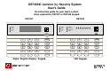
DS7400Xi (version 3+) Security System User’s Guide An instruction guide for your alarm system when used with a DS7447 or DS7445 keypad DS7447 DS7445 Armed Armed Perimeter Status Status Supervisory Power Power Bell Silenced Fire Fire Trouble 1 2 3 4 5 6 7 8 On On 1 2 3 Off 1 2 3 Off 4 5 6 Perimeter Only 4 5 6 Perimeter Only 7 8 9 No Entry 7 8 9 No Entry * 0 # Bypass * 0 # Bypass System Reset System Reset Alpha “English Display” Keypad LED Keypad
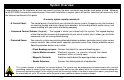
System Overview Congratulations on the installation of your new security system. No other investment can provide such peace of mind. Welcome to the DS7400Xi intrusion/fire control system. Since each installation is unique, yours will contain some, but not necessarily all of the features mentioned in this guide. A security system usually consists of: • A Control Panel: The control panel is the center of your intrusion/fire alarm system.
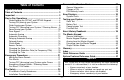
Personal Identification Numbers ...................................... 27 Table of Contents System Overview ................................................................. 2 Table of Contents ................................................................. 3 Important .............................................................................. 3 Day to Day Operations ........................................................ 4 Understanding the DS7447 and DS7445 Keypads ..............
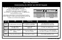
Day to Day Operations Understanding the DS7447 and DS7445 Keypads This chart will help you understand what each Light/LED on a Standard keypad represents. (For Master keypad operation, see page 37.) The DS7447 is an alpha-numeric LCD keypad. The DS7445 is an LED keypad; its LEDs 1-8 represent the first 8 zones of the system.
Understanding the DS7447 and DS7445 Keypads (continued) These Lights Present on the DS7445 Only: Light Off Flashing On Perimeter (yellow) Panel is disarmed or is not armed Perimeter. This Light will not flash. The perimeter is armed. Supervisory (yellow) There are no supervisory alarms present. A supervisory condition exists. This Light will not turn on steady. Bell Silenced (red) The bells do not need to be or have not been silenced. This Light will not flash.
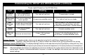
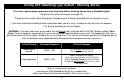
Turning ON (arming) your System This chart explains the five normal ways to arm the system from a Standard keypad. (For a Master keypad see page 37.) The green Status Light must be on steady and the display* must read “Ready to Arm” in order to arm the system with one of these commands. If the green Status Light is not on, or if the display* is reading “Not Ready,” see Force Arming or Zone Bypass for other ways to arm the system.
Type of Arming Desired Command Sequence Perimeter Arming Someone still on the premises. [PIN] + [Perimeter Only] The entry/exit delay is in effect. Custom Arming (If programmed) Ask your installing company to explain the type of arming that occurs when using this command. [PIN] + [#] + [4] Maximum Security Arming No one left on the premises. [PIN] + [No Entry] + [On] There is NO entry delay in effect. An alarm WILL occur upon entry. What will Happen The red Armed Light will begin to flash.
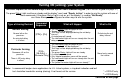
Quick Arming your System This chart explains four ways to quick arm the system from a Standard keypad. If Quick Arming is not used, a PIN must be entered at the beginning of all arming command sequences.
Turning OFF (disarming) your System / Silencing Alarms This chart explains proper procedures for disarming and/or silencing alarms from a Standard keypad. (To disarm from a Master keypad, see page 40.) Please read the section about Emergency Procedures prior to being confronted with an emergency event. If you have entered the building through a perimeter door, you may hear a steady pre-alert tone from the keypads. If so, disarm according to the chart below.
Force Arming your System This chart explains the procedure for Force Arming your system if one or more zones are faulted. When one or more zones are faulted, the system may be Force Armed (if programmed) by bypassing the faulted zones. The DS7447 display will read “Not Ready” and the DS7445's zone LEDs (1-8) will be on when Force Arming is required to arm the system. Force Arming during an AC power failure: Regular arming of the control panel is not permitted during an AC power failure.
Zone Bypass This chart explains the procedure for bypassing a faulted zone prior to arming the system. There may be occasions when it is desirable or necessary to temporarily bypass one or more zones prior to arming the system. Bypass commands only work when the control panel is disarmed. For instance, an open window may cause the DS7447 display to read “Not Ready” followed by the zone number. The DS7445 may have one of its zone 1-8 LEDs on steady.
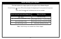
Automatic Arming Each partition can be programmed to automatically arm once per day. To program the Automatic Arming time, perform the following: Setting the Automatic Arming Time Enter a [Master PIN] + [#] + [0] Notes Setting the Automatic Arming Time can only be performed in the Master Programming Mode. Enter a [1] to enter the Automatic Arm Setup programming Enter the partition number. Press [#] to exit.
Automatic Disarming Each partition can be programmed to automatically disarm once per day. To program the Automatic Disarming time, perform the following: Notes Setting the Automatic Disarming Time Enter a [Master PIN] + [#] + [0] Setting the Automatic Disarming Time can only be performed in the Master Programming Mode. Enter a [4] to enter the Automatic Disarm Setup programming Enter the partition number. Press [#] to exit.
Delaying Automatic Arming This section explains how to delay the Automatic Arming Time. To inform occupants that the system is about to arm, a pre-arming period will begin 15 minutes before the system arms automatically. The keypad sounders, and any outputs programmed to follow the keypad sounders, will pulse five times every minute. During the last five minutes before arming, these sounders will be on steady. Once per minute the keypad (DS7447 only) will read, “Arm in nn min./PIN + OFF - extend.
Delayed Arming This section explains how to cause the system to arm after a specified number of hours. Delayed arming is simply causing the system to arm after a specified number of hours. To program the system for delayed arming, perform the following steps: Delaying Arming Notes Enter a [PIN] The keypad will display the following: Enter [9] [9] Arm in nn Hours # to accept to enter the Delayed Arming programming Enter number of hours to delay arming.
Chime Mode This chart explains the procedure for turning ON and turning OFF Chime Mode. Chime Mode causes the keypad sounders to beep each time a Perimeter or Entry/Exit zone is violated while the control panel is off (disarmed). The [#] [7] command is used to turn Chime Mode both off and on. This will only activate or de-activate the keypad(s) in the partition you are entering from.
Access Control This chart explains the procedure for activating devices that require an Access Control PIN. Your system may use a keypad key sequence to activate other electrical devices. The special PIN required to perform this function is known as an Access Control PIN. This feature can be used in armed or disarmed modes. Access PIN activations are recorded at the History Buffer. The PIN may control devices that activate for a short period of time (i.e. electric locking mechanisms on a door).
Changing the Date This chart will guide you through the steps necessary to Change the System Date. You should write down your entries before you enter the Master Code Programming Mode and have them with you as you begin programming. Make your entries promptly. If a delay of 15 seconds or more occurs between your entries, the 3-beep error tone occurs and exits you from the programming mode. It is recommended that this procedure be performed at a DS7447 keypad.
Changing the Expiration Date (for Temporary PINs) This chart will guide you through the steps necessary to Change the Expiration Date for Temporary PINs. You should write down your entries before you enter the Master Code Programming Mode and have them with you as you begin programming. Make your entries promptly. If a delay of 15 seconds or more occurs between your entries, the 3-beep error tone occurs and exits you from the programming mode.
Changing the Time This chart will guide you through the steps necessary to change the Time displayed at the keypads. You should write down your entries before you enter the Master Code Programming Mode and have them with you as you begin programming. Make your entries promptly. If a delay of 15 seconds or more occurs between your entries, the 3-beep error tone occurs and exits you from the programming mode. It is recommended that this procedure be performed at a DS7447 keypad.
Emergency Procedures Identifying Alarm Sounds Caution When Entering A Building Your alarm system may be programmed for a steady alarm sound or a pulsed alarm sound. It is important to learn the difference between a fire alarm sound and an intrusion alarm sound before you are confronted with an actual emergency. An alarm has occurred if: • The bells and sirens are on, and/or • The red Armed Light is flashing with the DS7447 display reading “Zone Alarm” • The DS7445 zone LEDs 1-8 are flashing.
Turning OFF (disarming) your System under Duress This chart explains the proper procedure for disarming under Duress. Ask your installer if the Duress feature has been activated. A Duress code is used when someone demands, by threatening your life or well-being, that the system be turned off. When used, the code will both turn off the system and report a silent Duress alarm if connected to a monitoring service.
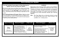
Emergency Keypad Alarms / Silencing Alarms Armed Armed Perimeter Status Status Supervisory Power Power Bell Silenced Fire Fire Trouble 1 2 3 4 5 6 7 8 On On 1 2 3 Off 1 2 3 Off 4 5 6 Perimeter Only 4 5 6 Perimeter Only 7 8 9 No Entry 7 8 9 No Entry # Bypass # Bypass * 0 * 0 System Reset System Reset A B A C B C The Emergency Alarm Keys [A], [B], and [C] may generate Fire, Special Emergency and Panic Alarms if programmed by the installer.
Fire Reset / Fire Trouble Fire Reset During a fire alarm, exit the premises immediately. When you have determined there is no fire, you must silence the bells/ sirens before you can initiate the System Reset command. [PIN] + [System Reset] Fire Trouble A Fire Trouble message with a zone number signifies a problem with the fire system, such as a break in the wiring that monitors smoke detectors. A Fire Trouble message with no zone number indicates a ground fault if the unit is in the Commercial Fire Mode.
Fire Safety WARNING: No fire detection device or system should be considered 100 percent foolproof. This fire alarm system can provide early warning of a developing fire. Such a system, however, does not ensure protection against property damage or loss of life resulting from a fire. Any fire alarm system may fail to warn for any number of reasons (i.e. smoke not reaching a detector that is behind a closed door).
Fire Safety (continued) • Provide a barricade between family members and fire, smoke and toxic gases (i.e. close all bedroom doors before retiring). • Children should be instructed on opening their bedroom windows and exiting safely from the building. If exiting is not possible, they should be taught to stay at the open window and shout for help until it arrives. • In the event of a fire alarm after retiring, wake the children by shouting to them from behind your closed door.
Personal Identification Numbers General Information When programming Personal Identification Numbers, it is helpful to know the following terms: • PIN: Personal Identification Number. This is the 4 digit code users must enter at the keypad to gain access to the system. A PIN may be assigned to each User Number 001 through 090. • User Number: This is the number that identifies each person using the system. There are 90 possible User Numbers available for use (001 through 090).
Personal Identification Numbers (continued) This chart will guide you through the steps necessary to change a PIN. You should write down your entries before you enter the Master Code Programming Mode and have them with you as you begin programming. Make your entries promptly. If a delay of 15 seconds or more occurs between your entries, the 3-beep error tone occurs and exits you from the programming mode. It is recommended that this procedure be performed at a DS7447 keypad.
Personal Identification Numbers (continued) PIN Authority Levels 0 = Master: Can enter all commands, add or change PINs in assigned partitions, change the time and date, bypass, arm, disarm, perform system tests, system reset and view history. User Number 001 must have the Master authority level. Any or all PINs can behave as a Master code. 1 = Unlimited: Can enter all commands, bypass, arm, disarm, system reset and perform system tests. It can not change PINs. 2 = General: Can bypass, arm and disarm.
Error Displays This chart explains the procedure for reading Error messages when the green Power Light is flashing. Clear the Error Display only on the advice of your installing company To Clear a display, enter [PIN] + [System Reset]. or if you are certain the problem has been remedied. Error Message Meaning DS7445 DS7447 Power Light (green) flashing Control Trouble Enter #87 LED 1 on AC Power Failure Battery Trouble LED 2 on Note: There is an Error Message.
System Faults System faults are designated as follows:System Faults are designated as follows: [#] [8] [9] will display [#] [8] [7] will display RAM Fault System fault 01 ROM Fault System fault 02 EEPROM Fault System fault 03 Ground Fault System fault 04 2Ph/Bell Fault = loss of communication to DS7420i System fault 10 Line 1 Fault = DS7420i phone line 1 fault System fault 11 Line 2 Fault = DS7420i phone line 2 fault System fault 12 Bell Fault = DS7420i bell circuit fault System fault 13 A
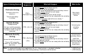
Testing your System This chart explains the procedure for performing a Zone Test. It is recommended that the system be tested weekly. The Zone Test is used to confirm that detectors will report alarms to the keypad. A Zone Test works on all zones, except 24-hour zones and fire zones. While the keypad is in a Zone Test, no control panel alarms will activate an alarm, except 24-hour zone alarms and fire alarms; these will override the Zone Test function.
Testing your System (continued) This chart explains the procedure for performing a Battery Test. If a power failure occurs, your control panel has a built-in battery that will continue to power the control panel for many hours. The control panel automatically recharges the battery when power is restored. In addition to an automatic battery test performed every 2 minutes, the battery may also be tested manually.
Testing your System (continued) This chart explains the procedure for performing a Communicator Test. This test is available only if your system transmits alarms and system information to a monitoring service, and has been programmed by the security installing company to permit communicator tests. This test can be performed from a Master Keypad. The account code for partition #1 will be used. A long beep will initially sound to acknowledge the start of the test.
Testing your System (continued) This chart explains the procedure for performing a Fire Walk Test. This test is used to confirm that Smoke detectors will report alarms to the keypads. The Fire Walk Test tests all fire zones, including verified fire and waterflow. At the start of the Fire Walk Test a Fire Walk Test report, if programmed, is sent to the central station. Fire alarm reports are not sent to the central station during the Fire Walk Test.
Event History Readback This chart explains the procedure for performing an Event History Readback. The History Buffer stores the last 400 events in memory. The DS7447 can display all of these events. The DS7445 will only display those zones (1-8) that have alarmed since the last Event History Readback. Type of Test Event History Readback* Command Sequence What will Happen What to Do [PIN] + [#] [8] [9] DS7447: The last event to take place will be displayed.
The Master Keypad - DS7447 only Your system may include a Master keypad. A Master keypad is a DS7447 keypad programmed to give a user access to all the partitions he has access to, not just the partition the Master keypad is in. This is different from a Standard keypad in that Standard keypads only give access to the single partition they are in. Commands entered at the Master keypad will affect all the partitions the user has access to.
Master Keypad Displays - DS7447 only This chart will help you understand what each Light function of the Master keypad represents. Light Off Flashing On Armed (red) All partitions are disarmed. One or more partitions are armed, or an alarm has occurred. All partitions are armed, and no alarms have occurred. Status (green) Not ready to arm (if the Armed Light is on, all partitions are armed). One or more zones are bypassed. All partitions are ready to arm.
Arming from the Master Keypad - DS7447 only This chart will help you to Arm from the Master keypad. Arming from the Master keypad Arming all the Partitions you have access to Enter your PIN followed by one of the arming sequences. This will arm all of your partitions, even if some are already armed. You must enter Single Partition Mode to arm the necessary partitions one at a time (see page 39). Arming only some of your Partitions 1. 2. 3. 4. 5. 6. 7.
Disarming from the Master Keypad - DS7447 only This chart will help you to Disarm from the Master keypad. Disarming from the Master keypad Disarming all the Partitions you have access to Enter your PIN followed by the [Off] key. This will disarm all of your partitions, even if some are already disarmed. You must enter Single Partition Mode to disarm the necessary partitions one at a time (see page 39). Disarming only some of your Partitions 1. 2. 3. 4. 5. 6. 7.
Single Partition Mode - DS7447 only Single Partition Mode is used to control partitions on a “one at a time/one by one” basis from the Master keypad. To enter the Single Partition Mode, enter your [PIN], then press the [#] key twice. This will call up the first partition you have access to. Enter the command sequence you wish for this partition. You do not need to use your PIN again. To move on to the next partition you have access to, press the [#] key twice.
Glossary Access Control PIN An Access Control PIN is a special code used to activate electric door locks or other mechanisms connected to the control panel that require this code to turn them on or off. Armed/Disarmed Arming the system (burglar zones) means to turn it on. Disarming the system means to turn it off. Remember, fire protection (if installed) is always Armed/on.
Glossary (continued) Installing Company The Installing Company is the company that physically installed the system. It may or may not be the same company who monitors the system. Partitioning Partitioning divides the system into 2, 3, 4, 5, 6, 7, or 8 areas or partitions. This allows the system to act as 2, 3, 4, 5, 6, 7, or 8 separate systems. Local System A Local System is a system that has a control panel that is not programmed to call a monitoring service.
Index Access Control ................................. 17 Access Control PIN ................... 17, 42 Alarm Sounds .................................. 21 Armed Light ................................. 4, 38 Arming .... 6, 7, 8, 10, 12, 15, 37, 39 Authority Levels ................................ 29 Backlight Control ................................ 5 Battery Test ...................................... 33 Bell Silenced Light .............................. 5 Central Station .................................
Quick Reference Guide Maintenance and Service The system should be tested weekly to ensure it is functioning properly. If problems are detected in testing or changes are noticed in normal operation, call your installing company for service. The manufacturer recommends replacing the system battery every 3 to 5 years. Monitoring Service Phone No. ______________________________ Monitoring Service System No. ______________________________ Installing Company Phone No.
Quick Reference Guide (continued) Zone Protection 65 _______________ 66 _______________ 67 _______________ 68 _______________ 69 _______________ 70 _______________ 71 _______________ 72 _______________ 73 _______________ 74 _______________ 75 _______________ 76 _______________ 77 _______________ Zone Protection 78 _______________ 79 _______________ 80 _______________ 81 _______________ 82 _______________ 83 _______________ 84 _______________ 85 _______________ 86 _______________ 87 _______________ 88 ____
System Features Reference Guide Audible Alarm Signalling Device Sounds Intrusion ( ) Pulse ( ) Continuous Fire ( ) Pulse ( ) Continuous Force Arming Enter an arming command sequence followed by the [Bypass] key. The maximum number of zones that can be forced armed is _____ Keypad Supplemental Alarm [B] Key ( ) Continuous ( ) Silent This system has the Duress Alarm feature. ( ) Yes ( ) No This system has the communicator test feature.
System Features Reference Guide (continued) Commands for Other System Features Chime Mode [PIN] + [#] [7] Zone Test [PIN] + [#] [8] [1] Battery Test [PIN] + [System Reset] Communicator Test [PIN] + [#] [8] [2] Error Display [PIN] + [#] [8] [7] Error Display Reset [PIN] + [System Reset] Fire Reset [PIN] + [System Reset] Event History Readback [PIN] + [#] [8] [9] Fire Walk Test [PIN] + [#] [9] [1] Access Control Enter your [Access Code PIN] followed by [Off].