
Specifications


DS9370 TriTech Ceiling Mount
PIR/ Microwave Intrusion Detector
1.0 Specifications
• Dimensions (HxDia): 3.5 in. x 7 in. (8.9 cm x 17.8 cm)
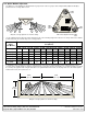
• Coverage: 360° by 70 ft. (21.3 m) diameter
coverage when mounted on 12 to 25 ft.
(3.7 to 7.6 m) high ceilings. A coverage
area of 40 ft. (12.2 m) is available when
mounted at 8 ft. (2.4 m) and a coverage
of 50 ft. (15.2 m) is available when
mounted at 10 ft. (3 m). The pattern
consists of 69 zones grouped into 21
barriers. Each barrier is 35 ft. (10.7 m)
long and 5 ft. (1.5 m) wide at 35 ft. (10.7
m). The barriers are divided into 3 groups
of 7 barriers, each of which has a vertical
adjustment for custom coverage.
• Input Power: 9.0 to 15.0 VDC; 29 mA standby, 39 mA
in alarm with LEDs enabled, and 49 mA
max current. Use only an Approved
Limited Power Source.
• Standby Power: There is no internal standby battery.
29 mAh is required for each hour of
standby time needed. For UL Listed
Requirements, four hours of standby
current (116 mAh) is required. Standby
power must be provided by an Approved
Limited Power Source.
• Sensitivity: Low/High settings.
• Alarm Relay: Silent-operating Form “C” relay. Contacts
rated 125 mA, 28 VDC, 3 watts
maximum for DC resistive loads. The
contacts transfer on alarm for a period of
4 seconds. Some countries require the
relay to be connected to a SELV
(Safety Extra-Low Voltage) circuit only.
Do not use with capacitive or inductive
loads.
• Tamper: Normally Closed (with cover in place)
tamper switch. A wall (base) tamper is
included. Contacts rated at 28 VDC, 125
mA, 3 watts maximum. Some countries
require the switch to be connected to a
SELV (Safety Extra-Low Voltage) circuit
only. Connect tamper circuit to a 24-hour
protection circuit.
• Temperature Range: The storage and operating range is -40°
to +120°F (-40° to +49°C). For UL Listed
Requirements, the range is +32° to
+120°F (0° to +49°C).
• Microwave Frequencies:
DS9370:10.525 GHz
DS9370-C: 10.588 GHz
(Export only. Not UL Listed)
• Countries of Intended Use: These products are intended for use
in the following countries within the European Union and in other
countries outside of the European Union:
• DS9370:Austria, Belgium, Denmark, Finland, Greece,
Luxembourg, Netherlands, Norway, Spain, Sweden.
• DS9370-C: United Kingdom, Ireland, France.
• US Patent Numbers: This detector is protected by one or
more of the following: #4,660,024; 4,764,755; 5,077,548;
5,208,567; 5,262,783; and 5,450,062. Other patents pending.
• Compliance: This device complies with Part 15 of the FCC
Rules and with RSS-210 of Industry and Science Canada.
Operation is subject to the following two conditions:
(1) this device may not cause harmful interference, and
(2) this device must accept any interference received,
including interference that may cause undesirable
operation.
Changes or modifications not expressly approved by Detection
Systems, Inc. can void the user’s authority to operate the
equipment.
2.0 Installation Considerations
• Never install the detector in an environment that causes an
alarm condition in one technology. Good installations start with
the LED OFF when there is no target motion. It should never be
left to operate with the tri-color LED in a constant or intermittent
green, yellow, or red condition.
NOTE: Microwave energy will pass through glass and most
common non-metallic construction walls.
• Avoid installations where rotating machines (e.g. ceiling fans)
are normally in operation within the coverage pattern. Point the
unit away from glass exposed to the outdoors and objects that
may change temperature rapidly. Avoid mounting the unit within
1 ft. (0.3 m) of any fluorescent light fixture.
Note: The PIR detector will react to objects rapidly changing
temperature within its field-of-view.
• Eliminate interference from nearby outside sources.
3.0 Mounting
• Select a location likely to intercept an intruder moving across
the coverage pattern. Recommended mounting height range is
12 to 25 feet (3.7 to 7.6 m). A coverage area of 40-70 ft. (12.2-
21.3 m) is available when mounted between 8-12 ft. (2.4-3.7 m).
• The surface should be solid and vibration-free. (i.e. drop tiles
should be secured if the area above the tiles is used as an air
return for HVAC systems).
• To open the detector, locate the arrow on the cover of the
detector . Turn a screwdriver in the recess between the
cover and the base . One side of the cover will remain
attached to the base of the detector.