
Installation Manual
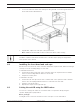
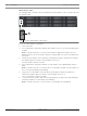
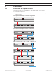
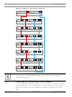
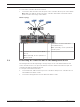
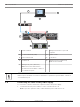
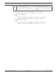

Table Of Contents
- Table of contents
- 1 Safety
- 2 Before you begin
- 3 System overview
- 4 Installation
- 5 Connection
- 6 Turning on/off AC power
- 7 Configuring the storage system
- 8 Maintenance
- Blank Page
- Blank Page
- Blank Page

28 en | Connection DSA E-Series (E2800 12-bay)
2018.02 | V1 | DOC Installaton manual Bosch Sicherheitssysteme GmbH
12-bay single controller unit
LN K LN K
P1 P2
0b
0a
e0c e0d
LN K LN K
P1 P2
0b
0a
e0c e0d
LN K
LN K
P1 P2
0b
0a
e0c
e0d
LN K
LN K
P1 P2
0b
0a
e0c e0d
1
23 4
5
6
Controller A
1 Management port1 (Ethernet)
Note: Used as default.
2 Management port 2 (Ethernet)
Note: Reserved for maintenance
operations if the hardware contains a
second Ethernet port.
3 Channel3 (iSCSI, optical) 4 Channel4 (iSCSI, optical)
5 Channel5 (iSCSI, RJ45 Base‑T) 6 Channel6 (iSCSI, RJ45 Base‑T)
Single controller units support 2different cabling options for the iSCSI ports.
– Default: iSCSI, RJ45 Base‑T
– Alternatively: iSCSI, optical
12-bay dual controller unit
LN K LN K
P1 P2
0b
0a
e0c e0d
LN K LN K
P1 P2
0b
0a
e0c e0d
LN K
LN K
P1 P2
0b
0a
e0c e0d
LN K
LN K
P1 P2
0b
0a
e0c e0d
Controller BController A
1
23 4
5
6
1
23 4
5
6
1 Management port1 (Ethernet)
Note: Used as default.
2 Management port 2 (Ethernet)
Note: Reserved for maintenance
operations if the hardware contains a
second Ethernet port.
3 Channel3 / ControllerA and
Channel3 / ControllerB (iSCSI,
optical)
4 Channel4 / ControllerA and
Channel4 / ControllerB (iSCSI,
optical)