DSA E-Series (E2800 12-bay) DSA-N2E8X4-12AT | DSX-N1D8X4-12AT | DSA-N2C8X4-12AT | DSA-N2E8X8-12AT | DSX-N1D8X8-12AT | DSA-N2C8X8-12AT | DSA-N2E8XA-12AT | DSX-N1D8XA-12AT | DSA-N2C8XA-12AT | DSA-N2E8XC-12AT | DSX-N1D8XC-12AT | DSA-N2C8XC-12AT en Quick Installation Guide
DSA E-Series (E2800 12-bay) Table of contents | en 3 Table of contents 1 Safety 4 1.1 Safety message explanation 4 1.2 Safety precautions 4 1.3 Important safety instructions 4 1.4 Warning notices 6 1.5 Caution notices 7 1.6 Notices 7 2 Before you begin 9 2.1 Hardware registration 9 2.2 Additional equipment 9 2.3 Additional documentation 9 3 Device views 10 4 Installation 13 4.1 Installing a 2U 12-bay unit 13 4.
en | Safety DSA E-Series (E2800 12-bay) 1 Safety 1.1 Safety message explanation Notice! Indicates a situation which, if not avoided, could result in damage to the equipment or environment, or data loss. Caution! ! Indicates a hazardous situation which, if not avoided, could result in minor or moderate injury. Warning! ! 1.2 Indicates a hazardous situation which, if not avoided, could result in death or serious injury.
DSA E-Series (E2800 12-bay) – Safety | en 5 The plug-socket combination must be accessible at all times, because it serves as the main disconnecting device. – Any openings in the unit enclosure are provided for ventilation to prevent overheating and ensure reliable operation. Do not block or cover these openings. – Do not place the unit in an enclosure unless proper ventilation is provided, or the manufacturer's instructions have been adhered to.
en | Safety DSA E-Series (E2800 12-bay) – The device performance is noticeably changed. – Installation of the unit must comply with local and national electrical codes. – Cluster media converters must be installed in a restricted access location. – When installing the unit into a movable cabinet or rack, install from the bottom up for best stability. – Use only manufacturer’s supplied power cords and cables with manufacturer equipment.
DSA E-Series (E2800 12-bay) Safety | en 7 Warning! ! To prevent electrical shock hazard, disconnect all power cables from the electrical outlet before relocating the system. Warning! ! Risk of bodily injury, A lead-acid battery can weigh up to 10.9kg (24.1lb). When you remove this type of battery, be prepared to support its weight. If the battery is dropped, the impact might cause bodily injury, including deep puncture wounds caused by the battery pins.
en | Safety DSA E-Series (E2800 12-bay) Notice! Video loss is inherent to digital video recording; therefore, Bosch Security Systems cannot be held liable for any damage that results from missing video information. To minimize the risk of losing information, we recommend multiple, redundant recording systems, and a procedure to back up all analog and digital information. Disposal Your Bosch product has been developed and manufactured using highquality materials and components that can be reused.
DSA E-Series (E2800 12-bay) Before you begin | en 2 Before you begin 2.1 Hardware registration 9 To log on to your existing account or to create a new user account: 1. If you already have a registered account, you can log on to it and add your new DSA E‑Series hardware to your existing account. 2. If you are a new customer, fill in the registration form and send it to Bosch ST Service organization (mailto:RMADesk.STService@de.bosch.com).
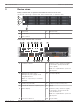
en | Device views 3 DSA E-Series (E2800 12-bay) Device views 12-bay controller unit or expansion unit with bezel removed - front view (Front view of the single controller unit, dual controller unit, or expansion unit) 1 2 3 4 5 1 Power LED 2 Attention LED 3 Locate LED 4 7-segment display 5 Drive canister 12-bay single controller unit - rear view 1 2 3 9 1 5 4 6 7 8 10 11 12 13 Controller canister 14 2 Channel 3 (left) / Channel 4 (right) Host interface ports (Dual 10 GB iSCSI
DSA E-Series (E2800 12-bay) Device views | en 13 Mains connection 100 - 240 VAC 14 11 Power-fan canister 2 12-bay dual controller unit - rear view 1 2 3 4 9 1 5 6 7 8 10 11 12 13 Controller A 14 2 Channel 3 (left) / Channel 4 (right) Host interface ports (Dual 10 GB iSCSI, optical) Note: Use only RJ45 Base‑T ports or optical ports. 3 Management port 1 (left) / 4 Serial port (RJ45) Management port 2 (right) - Dual 1 Gigabit Ethernet Note: Use only Port 1 per controller (default).
en | Device views DSA E-Series (E2800 12-bay) 1 IOM A 2 IOM A - SAS port 1 3 IOM A - SAS port 2 4 IOM A - SAS port 3 5 IOM A - SAS port 4 6 IOM B 7 IOM B - SAS port 1 8 IOM B - SAS port 2 9 IOM B - SAS port 3 10 IOM B - SAS port 4 11 Power-fan canister 1 12 On/off switch 13 Mains connection 100 - 240 VAC 14 Power-fan canister 2 See also – 2017.
DSA E-Series (E2800 12-bay) Installation | en 4 Installation 4.1 Installing a 2U 12-bay unit 13 You can install the unit in a four-post rack or system cabinet. Observe the following: – You can install the unit in either a square-hole or round-hole rack. – If you are installing the unit in a cabinet not provided by Bosch, you must calculate the thermal output of your equipment and compare the results with the target system cabinet's thermal rating.
en | Installation DSA E-Series (E2800 12-bay) Caution: A fully loaded unit weighs approximately 65 lb (29 kg). Two persons or a mechanical lift are required to safely move the unit. 4. Carefully slide the unit all the way onto the rails. Note: If applicable, you might need to remove the end caps or the system bezel to secure the unit to the rack post. Replace the end caps or bezel when you are done. Note: You might need to adjust the rails to ensure that the unit slides all the way onto the rails.
DSA E-Series (E2800 12-bay) 6. Installation | en 15 Secure the unit to the back of the rails by inserting two M5 screws through the brackets at the unit and the rail kit bracket. 7. If applicable, replace the end caps or the system bezel. Note: Additional documentation can be found on the Bosch online catalog. Notice! Install the expansion units below and above the controller unit, keeping the weight in the lower portion of the cabinet. 4.
en | Connection DSA E-Series (E2800 12-bay) 5 Connection 5.1 Connecting the expansion units The expansion units are shipped with the appropriate number of SAS cables. To connect the components: 4 Connect the SAS cable from the SAS port on the controller unit to the SAS port on the expansion unit.
DSA E-Series (E2800 12-bay) Connection | en 17 Maximum configuration - dual controller configuration Controller A Controller B IOM A IOM B IOM A IOM B IOM A IOM B IOM A IOM B IOM A IOM B IOM A IOM B IOM A IOM B Notice! You can connect a 12-bay DSA E2800 controller unit to a maximum of seven 12-bay DSA E2800 expansion units. Bosch Sicherheitssysteme GmbH Quick Installation Guide 2017.
en | Connection 5.2 DSA E-Series (E2800 12-bay) Connecting the controller unit to the network In case of a Bosch Video Recording Solution a host is an IP camera. To connect the controller unit to the Ethernet one or two of two available iSCSI host ports must be connected to the Ethernet. The iSCSI port connections will then be used by the IP cameras for video data traffic.
DSA E-Series (E2800 12-bay) Connection | en 19 1 3 2 4 6 7 5 8 1 9 Private network 2 Management station or personal computer 3 Local Area Network (LAN) 4 Switch or hub 5 Dual controller unit 6 Controller A 7 Controller B 8 Management port 1 (Ethernet) Note: Used as default. 9 Management port 2 (Ethernet) Note: Reserved for maintenance operations if the hardware contains a second Ethernet port.
en | Connection DSA E-Series (E2800 12-bay) 2. Connect the two power cords of the controller unit to different power distribution units in the cabinet or rack. Note: If you have expansion units, connect the two cords accordingly. 1 1 = Power switch 3. If you have expansion units, turn on their two power switches first. Note: Wait for 2 minutes to allow hard disks to spin up before applying power to the controller unit. 4.
DSA E-Series (E2800 12-bay) Connection | en 21 12-bay single controller unit Controller A LN K LN K P1 0a 0b P2 e0c e0d LN K LN K P1 0a 0b P2 e0c e0d LN K LN K P1 0a 0b P2 e0c e0d LN K LN K P1 0a 0b P2 e0c e0d 3 1 4 1 2 6 5 Management port 1 (Ethernet) 2 Management port 2 (Ethernet) Note: Used as default. Note: Reserved for maintenance operations if the hardware contains a second Ethernet port.
en | Connection DSA E-Series (E2800 12-bay) 5 Channel 5 / Controller A and 6 Channel 6 / Controller A and Channel 5 / Controller B (iSCSI, RJ45 Channel 6 / Controller B (iSCSI, RJ45 Base‑T) Base‑T) The Multipathing feature is enabled on dual controller units by default. Dual controller units support 2 different cabling options for the iSCSI ports.
DSA E-Series (E2800 12-bay) Turning on/off AC power | en 6 Turning on/off AC power 6.1 Turning on AC power 23 Make sure the Ethernet cable is connected to the management host. The default IP addresses will take three minutes to initialize from the time the network is attached. The default IP addresses are: – Controller A, Port 1: 192.168.128.101 – Controller B, Port 1: 192.168.128.102 Notice! DHCP is attempted for the first three minutes of attaching the network cables.
en | Installing and configuring the storage array 7 DSA E-Series (E2800 12-bay) Installing and configuring the storage array For the basic setup use the Video Recording Manager Configuration Manager software. For detailed information, in Configuration Manager refer to the Video Recording Manager Help. More information For more information, software downloads, and documentation, visit www.boschsecurity.com and go to the respective product page. 2017.
Bosch Sicherheitssysteme GmbH Robert-Bosch-Ring 5 85630 Grasbrunn Germany www.boschsecurity.