
Installation Manual
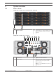
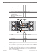
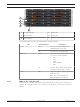
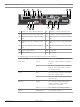
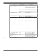
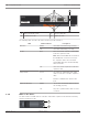
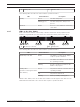
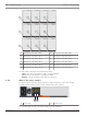
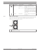
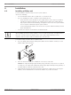
Table Of Contents
- Table of contents
- 1 Safety
- 2 Before you begin
- 3 System overview
- 4 Installation
- 5 Connection
- 6 Turning on/off AC power
- 7 Configuring the storage system
- 8 Maintenance
- Blank Page
- Blank Page
- Blank Page

12 en | System overview DSA E-Series (E2800 60-bay)
2018.02 | V1 | DOC Installation manual Bosch Sicherheitssysteme GmbH
5 Management port1 (left) /
Management port2 (right) - Dual
1Gigabit Ethernet
Note: Use only Port1 per controller
(default).
6 Serial port (RJ45)
7 Serial port (mini USB) 8 USB port (only for factory use)
9 Dual 12Gb SAS drive expansion ports 10 Status display
11 Channel5 (left) / Channel6 (right) -
Host interface ports (Dual 10GB
iSCSI, RJ45 Base‑T)
Note: Use only RJ45 Base‑T ports or
optical ports.
12 ControllerB (see ControllerA)
60-bay expansion unit - rear view
5
6 7
11
4
9 108 12 13 14
2
3
1
1 Mains connection 240VAC 2 On/off switch
3 IOMA 4 IOMA - SAS port1
5 IOMA - SAS port2 6 IOMA - SAS port3
7 IOMA - SAS port4 8 Mains connection 100 - 240 VAC
9 On/off switch 10 IOMB
11 IOMB - SAS port1 12 IOMB - SAS port2
13 IOMB - SAS port3 14 IOMB - SAS port4
3.2 LED description
There are several LEDs on the front and rear of the chassis. The LEDs show the over-all status
of the system and the activity and health of specific components.
3.2.1 LEDs on the operator display panel
Each controller unit and expansion unit has LEDs located on the operator display panel. The
operator display panel is visible through the front bezel of a controller unit and through the
left end cap of an expansion unit.