DSDA iSCSI Disk Array Series DSA-S5B50 | DSA-N2B20 | DSA-N2B50 en Installation Guide
DSDA iSCSI Disk Array Series Table of Contents | en 1 Table of Contents 1 Precautions 3 2 Introduction 4 2.1 Systems at a Glance 4 3 Unpacking and Installing the Hardware 6 4 Delivery Status 7 5 Configuration through the Web Interface 8 5.1 Configuration of the Network Settings and Access to the Interface 5.2 Time and Date Settings 11 5.3 Configuring the Volume 12 5.4 Creating an Initiator Group 14 5.5 Creating LUNs 14 6 Adding Storage 17 6.
2 en | Table of Contents V 1 | 2008.
DSDA iSCSI Disk Array Series 1 Precautions | en 3 Precautions – The system is heavy even without disks installed. At least two people are required to install the system. – The rack cabinet into which this system will be installed must support overcurrent protection and must not be overloaded by the modules installed.
4 en | Introduction 2 DSDA iSCSI Disk Array Series Introduction This guide explains the installation of the digital storage systems of type – DSA-S5B50 – DSA-N2B20 – DSA-N2B50 for either direct storage of recorded video data or for use with the VRM Video Recording Manager application. Additional documentation is available on the internet and can be downloaded from www.boschsecurity.com under Product Catalog > CCTV > IP Video > Disk Arrays. 2.
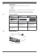
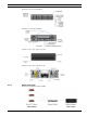
DSDA iSCSI Disk Array Series Introduction | en 5 Example front side (DSA-N2B20): Example rear side (DSA-N2B20): Expansion unit – disk shelf: Front side Expansion unit – disk shelf: Rear side 2.1.2 CCTV Integration Example for installation without VRM: Bosch Security Systems Installation Guide V 1 | 2008.
6 en | Unpacking and Installing the Hardware 3 DSDA iSCSI Disk Array Series Unpacking and Installing the Hardware NOTICE! i ! ! For more detailed information on the hardware installation please refer to the documentation available on www.boschsecurity.com under Product Catalog > CCTV > IP Video > Disk Arrays. WARNING! The storage system is heavy. Two people are required to lift a system. CAUTION! Only use the rail kit supplied with the system.
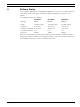
DSDA iSCSI Disk Array Series 4 Delivery Status | en 7 Delivery Status For use with the VRM Video Recording Manager application or for direct recording from Bosch cameras and senders, the system should be configured following the steps in the next chapter. Preconfigured settings upon delivery: DSA-S5B50 DSA-N2B20 DSA-N2B50 RAID type RAID-4 RAID-DP RAID-DP Volume vol0 with 2 disks vol0 with 3 disks vol0 with 3 disks IP address 10.10.10.10 10.10.10.10 10.10.10.10 IP address (2nd port) 10.10.
8 en | Configuration through the Web Interface 5 DSDA iSCSI Disk Array Series Configuration through the Web Interface NOTICE! i Do not use the S5B50 management software StoreVault Manager for the configuration. The DSA series come with a dedicated Bosch standardized system layout. StoreVault Manager is not compatible with the Bosch layout. Follow these steps to configure each system. This procedure is nearly identical for all three types of storage systems. 1. Turn on the system.
DSDA iSCSI Disk Array Series 2. Configuration through the Web Interface | en 9 Select from the Control Panel of your computer Network Connections, Properties. Here, configure your network interface to use IP address 10.10.10.9 with Subnet mask 255.0.0.0. Example screen: i NOTICE! The IP address 10.10.10.9 is an example. The IP addresses 10.10.10.10 and 10.10.10.11 are the default IP addresses for the storage system and cannot be used otherwise. 3.
10 en | Configuration through the Web Interface 5. DSDA iSCSI Disk Array Series Enter root as the user name, leave the password blank. The FilerView start page loads and shows an overview on the system status. 6. Click the FilerView icon. This opens the FilerView administration interface in a new window. On the left-hand side of the FilerView interface, you will see the navigation panel. For direct help on a specific topic, click one of the ?-buttons.
DSDA iSCSI Disk Array Series 8. Configuration through the Web Interface | en 11 Click Modify next to the network interface labeled e0a and configured with IP address 10.10.10.10. 9. Enter the IP address information for the network. Change IP Address and Netmask to the desired value. Leave Broadcast blank. Example screen: 10. Set Media Type to 10/100/1000 Mbit Auto-negotiate. Leave the Trusted option enabled. 11. Click Apply to confirm the changes.
12 en | Configuration through the Web Interface DSDA iSCSI Disk Array Series 19. The changes are summarized on the Commit screen. Click Commit to apply the new settings. NOTICE! i 5.3 If you are using the VRM Video Recording Manager application (Version 1.5 or higher), all further settings are made through VRM. If you use the digital storage systems for direct recording, continue with the following steps.
DSDA iSCSI Disk Array Series Configuration through the Web Interface | en 13 27. The changes are summarized on the Commit screen. Click Commit to apply the new settings. By default, one disk is left as a spare disk. If no spare disk is needed, this disk can be added to the volume manually. To do so, please continue with step 28. If you would like to keep the spare disk, please continue with step 32. 28. In the navigation panel, select Filer > Use Command Line. 29.
14 en | Configuration through the Web Interface 5.4 DSDA iSCSI Disk Array Series Creating an Initiator Group 32. In the navigation panel, select LUNs > Initiator Groups > Add. The Add Initiator Group screen displays. 33. Group Name: Enter VRM_UNITIGROUP0. 34. Type: Select iSCSI. 35. Operating System: Select Linux. 36. Initiators: Enter the initiator names of all cameras and senders that shall write to this system. The initiator name of a device is obtained from the Configuration Manager program.
DSDA iSCSI Disk Array Series Configuration through the Web Interface | en 15 The following procedure must be carried out for each LUN to be created. 39. In the navigation panel, select LUNs > Wizard. Click Next on the LUN Wizard welcome screen. 40. Path: Enter /vol/vol0/lun1. The first part of this path is always vol, the second part is the name of your volume (vol0), the third part is the name of your LUN (change this for all further LUNs you are creating).
16 en | Configuration through the Web Interface DSDA iSCSI Disk Array Series 47. On the Add Initiator Groups screen, click Next. 48. LUN ID: Leave this field blank. The lowest available ID will be used automatically. Click Next. 49. The changes are summarized on the LUN Wizard: Commit Changes screen. Click Commit to create the LUN. If the LUN has been created successfully, a Success! screen will display. 50. Use the LUN Wizard to create all 16 (or the desired number of) LUNs.
DSDA iSCSI Disk Array Series 6 Adding Storage | en 17 Adding Storage Storage shelves can be added to the DSA-N2B20 and the DSA-N2B50 system. Each expansion unit comes with 14 disks, 750 GB each. Shelves are daisy-chained in a so-called loop. The first shelf added to a storage system is directly connected to the storage system.
18 en | Adding Storage DSDA iSCSI Disk Array Series 2. Set the correct Shelf ID by pressing the + or – button at the back of the shelf, next to the ID display. Note: Do not use identical IDs for different shelves. 6.1.2 Connecting the Power Supplies 3. If not already done, power on the base unit. On the shelf, connect both power supplies and switch them on. Wait 30 seconds to allow the shelf to initialize.
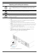
DSDA iSCSI Disk Array Series 6.1.3 Adding Storage | en 19 Connecting the Shelf 4. Connect the shelves using the supplied cables. – For the first shelf: Insert an SFP into the In port of each of the two I/O modules at the back of the shelf to convert them to optical ports, making sure that the SFP has the correct position before inserting it. Plug in one end of the optical cable to the In port of the lower I/O module on your shelf.
20 en | Adding Storage DSDA iSCSI Disk Array Series 9. Volume Parameters: Volume Name: Enter a name for the new volume. The name should consist of the word vol and the ID of the disk shelf you just added (e.g. the volume for the first shelf you are adding to your storage system will be vol1, the volume for the second shelf will be called vol2 and so on). Leave the second and third parameter to their default value and enable Double Parity. Click Next. 10. RAID Group Size: Set to 14. Click Next. 11.
DSDA iSCSI Disk Array Series Adding Storage | en 21 24. On the following two screens, click Next and leave all options to their default value. On the third screen (Other), uncheck Access Time. 25. The changes are summarized on the Commit screen. Click Commit to apply the new settings. 26. In the navigation panel, select Volumes > Snapshots > Configure. Choose the newly created volume from the drop-down list. Uncheck Scheduled. Click Apply to commit the change. 27.
22 en | Adding Storage 6.1.5 DSDA iSCSI Disk Array Series Creating LUNs For each newly created volume, you must create at least one LUN, as previously created LUNs cannot not be reconfigured to use them for the new volume. i NOTICE! The size of the LUNs for Bosch applications is limited to 2TB. 28. Create LUNs for the volume, as described in Section 5.5 Creating LUNs, page 14. Be sure to use the correct volume when setting the path for each LUN. Example: /vol/vol1/lun0 V 1 | 2008.
DSDA iSCSI Disk Array Series 7 Monitoring and Maintenance | en 23 Monitoring and Maintenance i NOTICE! You can find more detailed documentation on www.boschsecurity.com under Product Catalog > CCTV > IP Video > Disk Arrays. 7.1 Monitoring the System 7.1.1 Using the FilerView Monitor The system should be monitored. An overall system status monitor is provided by the FilerView administration interface. 1.
24 en | Monitoring and Maintenance DSDA iSCSI Disk Array Series 7.2 Maintenance 7.2.1 Disk Replacement DSA-S5B50 Follow these steps to replace a disk: 1. Remove the new disk drive from the antistatic bag. 2. Determine the disk drive to be replaced, see Section 7.5.1 DSA-S5B50, page 30. 3. Press the release latch of the drive. Swing the drive bay cover to the right until it is at a right angle to the chassis. 4. 5. Slide the entire assembly toward you in order to pull it out of the drive bay.
DSDA iSCSI Disk Array Series Monitoring and Maintenance | en 3. Rotate the handle to extract the disk. 4. Support the bottom of the drive to remove it. 5. 25 Reverse these steps to replace the hard disk. The drive LED should be lit green now. 7.2.3 Replacement of Modules Documentation on the replacement of other modules is available on www.boschsecurity.com under Product Catalog > CCTV > IP Video > Disk Arrays. Refer to these documents: Bosch Security Systems – Replacing CF Card.
26 en | Monitoring and Maintenance DSDA iSCSI Disk Array Series 7.3 Hardware Troubleshooting 7.3.1 DSA-S5B50 LEDs on front side, left: If the Power Indicator is not lit green, the system has no power. X Check the cables and press the power button. If the Ethernet Link LED is not lit, no network connection is established. 1. Check if the cable is plugged in at both ends. 2. Check the cable and, if neccessary, replace it.
DSDA iSCSI Disk Array Series 7.3.2 Monitoring and Maintenance | en 27 DSA-N2B20 / DSA-N2B50 LEDs on front side, right: If the Power LED is not lit green, the system has no power. X Check the cables and switch the system on. If the Fault LED is lit amber, the system is halted, or an error is indicated. A blinking Controller LED indicates activity of the controller. A corresponding Power LED and a Fault LED are also located on the rear side of the system.
28 en | Monitoring and Maintenance DSDA iSCSI Disk Array Series There are four LEDs on the power supply unit on the rear side of each shelf. If either the Fan LED or the Power LED are lit amber, the power supply unit must be replaced. At the front side of each disk drive, there are two LEDs. 7.4 – If no LED is lit, the drive is not recognized. Reinsert the drive. – If one LED is lit amber, a fault is indicated. The drive must be replaced.
DSDA iSCSI Disk Array Series 1. Monitoring and Maintenance | en 29 Upload the new software to a Web server – If you are using VRM, place the file that contains the new version in C:\Program Files\Bosch\Video Recording Manager\VRM Server\web on your VRM Server. – If you are not using VRM, start a Web server tool, for example MiniWebServer.exe, select a root directory and copy the new software version into this root directory. Example screen: 2.
30 en | Monitoring and Maintenance 5. DSDA iSCSI Disk Array Series If a new mainboard firmware comes with the release (check the release notes), on the console, at the prompt LOADER>, enter update_flash. 6. If a new BMC firmware comes with the release (check the release notes), on the console, at the prompt LOADER>, enter update_bmc. 7. On the console, enter: bye. The system reboots with the new software. 7.5 Disk Identification 7.5.1 DSA-S5B50 The disk drives are numbered from 0 to 11: 7.5.
DSDA iSCSI Disk Array Series 8 Technical Data | en 31 Technical Data For more detailed information, please refer to the data sheets with the latest information available on www.boschsecurity.com under Product Catalog > CCTV > IP Video > Disk Arrays. 8.1 Technical Specifications DSA-S5B50 8.1.1 Electrical Requirements AC power/Max current 100 V to 120 VAC, 9 A 200 to 240 VAC, 4.5 A 8.1.
32 en | Technical Data DSDA iSCSI Disk Array Series 8.2 Technical Specifications DSA-N2B20 8.2.1 Electrical Requirements – One Controller Module Input voltage: 100 to 120V 8.2.2 Worst case, System, single PSU two PSUs • input current measured 3.37 A 3.22 A • input power measured 332 W 316 W • thermal dissipation 1133 BTU/hr 1077 BTU/hr Input voltage: 200 to 240V Worst case, System, single PSU two PSUs • input current measured 1.69 A 1.
DSDA iSCSI Disk Array Series Technical Data | en 8.3 Technical Specifications DSA-N2B50 8.3.1 Electrical Requirements – One Controller Module Input voltage: 100 to 120V 8.3.2 Worst case, System, single PSU two PSUs • input current measured 5.07 A 4.51 A • input power measured 504 W 439 W • thermal dissipation 1718 BTU/hr 1497 BTU/hr Input voltage: 200 to 240V Worst case, System, single PSU two PSUs • input current measured 2.46 A 2.
34 en | Technical Data DSDA iSCSI Disk Array Series 8.4 Technical Specifications Disk Shelf Expansion Unit – DSX-N2X00-14AT 8.4.1 Electrical Requirements Input voltage: 100 to 120V Worst case, System, single PSU two PSUs • input current measured 3.42 A 3.22 A • input power measured 341 W 321 W • thermal dissipation 1163 BTU/hr 1095 BTU/hr Input voltage: 200 to 240V Worst case, System, single PSU two PSUs 1.63 A 1.60 A • input current measured 8.4.
DSDA iSCSI Disk Array Series 9 Trademarks | en 35 Trademarks Java is a trademark of Sun Microsystems. Data ONTAP and RAID-DP are trademarks of NetApp. Bosch Security Systems Installation Guide V 1 | 2008.
36 en | Trademarks V 1 | 2008.
Bosch Security Systems Robert-Koch-Straße 100 D-85521 Ottobrunn Germany Telefon 089 6290-0 Fax 089 6290-1020 www.boschsecurity.