DVR4C Installation manual EN Digital Video Recorder
DVR4C | Installation Manual | Table of Contents SAFETY PRECAUTIONS ..............................................................................................................................5 1. 2. 3. 4. 5. INTRODUCTION .........................................................................................................................................................................7 1.1 DIGITAL VIDEO RECORDER FOR SECURITY APPLICATIONS ......................................................
DVR4C | Installation Manual | Table of Contents 6. 5.3 STARTING THE CONFIGURATION TOOL .......................................................................................... 22 5.4 HOW TO LOG IN ........................................................................................................................................ 22 TECHNICAL SPECIFICATIONS ........................................................................................................................................
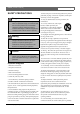
DVR4C | Installation Manual | SAFETY PRECAUTIONS Danger The lightning flash with arrowhead symbol, within an equilateral triangle, is intended to alert the user to the presence of an uninsulated “dangerous voltage” within the product's enclosure that may be of sufficient magnitude to constitute a risk of electric shock to persons.
DVR4C | Installation Manual | U.S.A. models only--Section 810 of the National Electrical Code, ANSI/NFPA No.70-1981, provides information with respect to proper grounding of the mount and supporting structure, grounding of the coax to a discharge unit, size of grounding conductors, location of discharge unit, connection to grounding electrodes, and requirements for the grounding electrode. 22.
DVR4C | Installation Manual | Introduction 1 Introduction 1.1 Digital video recorder for security applications The DVR4C is a video recording system that can record up to four camera signals with associated audio signals while simultaneously providing live multiscreen viewing and playback. The unit has comprehensive search and playback facilities for viewing stored video. Once set up, all recording takes place in the background without requiring operator intervention.
DVR4C | Installation Manual | Installation 2 EN | 8 Installation 6. Connect up to four alarm output relays via the terminal connector. > Relay 1 responds to an input alarm, Relay 2 responds to a To install the DVR make the connections described below and then enter the relevant data in the quick install menu. system failure and the other relays are assigned to the remote software. Configure the alarm outputs as N/O or 2.1 Connections N/C in the menu system. 7.
DVR4C | Installation Manual | Installation EN | 9 2.2 First-time use To open the quick install menu, press the MENU key on the front panel and select the Quick install submenu. Fill in the basic settings to get the unit operational. The unit begins recording automatically. Press the ESC key to close the menu. >>> DAYLIGHT SAVING • Select if DST is used (On) or not (Off). >>> DATE FORMAT • Select from three date formats which show either the month (MM), the day (DD) or the year (YYYY) first.
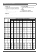
DVR4C | Installation Manual | Installation >>> SPEED (IPS) • Select the recording speed to be used for all cameras. • The Images Per Second (IPS) rates available for PAL range from 0, 0.75 (one image every 1.3 seconds), up to 25 IPS. • The IPS rates available for NTSC range from 0, 1 (one image every second), up to 30 IPS. EN | 10 >>> AUDIO RECORDING • Select On or Off to record Audio or not to record Audio. >>> APPLY • Select this item to save your settings.
DVR4C | Installation Manual | Operating instructions 3 EN | 11 Operating instructions In zoom mode, press to move the zoomed area to the left. The purpose of the front panel keys is explained here. The functions available can be limited by setting passwords. An administrator has access to many more functions in the menu. Refer to Menu System for a full list of available menu items. 3.1 8 Pause key: In live mode, press to freeze a camera picture. In playback mode press to pause playback.
DVR4C | Installation Manual | Operating instructions In playback mode, press to stop playback and to go back to live mode. In pause mode, press to go back to live mode. If the beeper sounds, press ESC to silence it. 12 Stop key: In playback mode, press to stop playback and to go back to live mode. In pause mode, press to go back to live mode. In menu mode, press to move the current selected position downwards. In zoom mode, press to move the zoomed area downwards.
DVR4C | Installation Manual | Operating instructions 3.3 Live, playback, copy and search modes 3.3.1 Live mode The live mode is the normal operating mode of the unit where you watch live pictures from the cameras. From the live mode you can switch to the search mode, the playback mode or to the system menu. Access to system menu, search and playback functions may require a password. Discuss this with your administrator.
DVR4C | Installation Manual | Menu system 4 Menu system You access all the parameters used to set up the unit via the menu system using the keys on the front of the unit itself. The PC-based Configuration Tool application allows you to access the menu system from a remote computer. 4.1 EN | 14 4.3 Camera Setup > Use the Camera Setup menu to access the submenus for setting the camera names, for locking cameras and for controlling cameras.
DVR4C | Installation Manual | Menu system EN | 15 4.4 Recording > 4.5 Event Setup > The overall schedule consists of 4 periods: Weekday Day, Weekday Night, Weekend Day and Weekend Night. The start and end time of each period is set in the Profiles menu. Recording conditions can be configured for each of the four periods. • • • • • >> RECORDING • Set the normal recording rate and quality to be used for all cameras. • Set the recording rate and quality that are used when an input alarm is triggered.
DVR4C | Installation Manual | Menu system 4.6 System Settings > Use the System Settings menu to get access to those items that are used to configure the system. >> LANGUAGE • A language is selectable from the list with the up/down scroll keys. Press the play key to confirm. >> AUDIO • An audio input can be set to record with its corresponding video input. Audio 1 is mapped to video 1, audio 2 to video 2, audio 3 to video 3 and audio 4 to video 4.
DVR4C | Installation Manual | Menu system • • • Fill in the IP, subnet mask and default gateway addresses when DHCP is set to Off. Fill in the DNS in order to use an e-mail address. At least one DNS should be specified. Set Auto-Detect to On to allow the Remote viewer software to automatically detect the DVR in a network. > Auto-Detect may not work when a firewall is between the DVR and the PC. • EN | 17 • Select the number of images to be sent attached to the e-mail (3 JPEG images by default).
DVR4C | Installation Manual | Menu system >> MONITOR SETUP >>> DISPLAY CAMERA WITH MOTION • Select if the DVR switches automatically to a full screen image of the camera when motion is detected on that camera. • With multiple motion detections shortly after each other, the last camera where motion was detected is used for display. >>> DISPLAY CAMERA WITH INPUT ALARM • Select if the DVR switches automatically to a full screen image of the camera when an input alarm becomes active for that camera.
DVR4C | Installation Manual | Menu system EN | 19 >>> REMOTE USERS • • • • • • • Login names and passwords for the remote users (4) and administrator can be specified here. The administrator login name is always "admin" and cannot be changed. The remote user login name can be upto 16 characters long. The remote user password can be up to 12 characters long. Access to playback (PB) and relay control (RL) is set for each remote user by placing a Y (allowed) or a N (not allowed).
DVR4C | Installation Manual | Menu system EN | 20 >> MISCELLANEOUS >>> CURRENT PROFILE • Shows the profile (Weekday - Day, Weekday - Night, Weekend - Day, Weekend - Night) that is currently active. The DVR firmware version is shown here. Select Factory defaults to set all parameters, except IP address, subnet mask, default gateway and disk setup, to their default values. >>> WEEK START AND WEEK END • Any day from Monday to Sunday can be used as a start date or end date of a week.
DVR4C | Installation Manual | Menu system 4.8 Disk Manager > The Disk Manager menu gives access to information on the internal hard disk(s). The status of the recorded video and associated data is also accessed via this menu. >> HISTORY • All system events are listed on a History log which cannot be deleted or changed. • Select a time frame to search by entering the start and end time. • To search for a specifc type of event, select a filter option: All, Input Alarm, Motion, Text, Error or Status.
DVR4C | Installation Manual | Using the Configuration Tool 5 Using the Configuration EN | 22 program via the Start button on the task bar and the Programs menu item. Follow the login procedure. Tool 5.4 How to Log in The Configuration Tool is a software application that makes the installation and configuration of a unit faster and easier. The Configuration Tool runs on a PC that is connected to the DVR via an Ethernet network connection.
DVR4C | Installation Manual | Using the Configuration Tool 3. Select a DVR and click OK. To add DVR to the list via PSTN: 1. Select Dial-in and fill in the name and phone number of the new DVR manually and click OK. > The phone number to be filled-in is set in the System settings/Connectivity/Network setup menu of the DVR. To control a particular DVR (only administrators can log in): 1. Select the DVR you want to control. 2. Type your user name and password. > The user name is always admin.
DVR4C | Installation Manual | Technical specifications 6 Technical specifications EN | 24 Recording resolution: 352 x 288 (PAL) / 352 x 240 (NTSC) Display modes Rated Voltage and Power Monitor: Full, full sequence, quad, alarm call-up 100-240 VAC; 0.7-0.3A, 50/60Hz Recording Modes Video Video standard: Live resolution: Digital Zoom: Compression: Inputs: Outputs: Linear, Continuous PAL/NTSC auto-detect 720x576 (PAL) / 720x484 (NTSC) 2 times MPEG4-based Composite video 0.
Bosch Sicherheitssysteme GmbH Bosch Security Systems B.V. Robert-Koch-Straße 100 P.O. Box 80002 D-85521 Ottobrunn 5600 JB Eindhoven Germany The Netherlands www.bosch-sicherheitssysteme.de www.boschsecuritysystems.com 3122 165 22981 © 2007 Bosch Security Systems B.V. Subject to change. Printed in Korea.