AutoDome® and EnviroDome® Indoor Pendant In-ceiling Model Installation Manual Version 5.
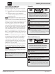
EN Important Safeguards Important Safeguards 1. Read, Follow, and Retain Instructions - All safety and operating instructions should be read and followed before operating the unit. Retain instructions for future reference. 2. Heed Warnings – Adhere to all warnings on the unit and in the operating instructions. 3. Attachments - Attachments not recommended by the product manufacturer should not be used, as they may cause hazards. 4.
EN For Indoor Product 1. Water and Moisture - Do not use this unit near water - for example, in a wet basement, in an unprotected outdoor installation, or in any area classified as a wet location. 2. Object and Liquid Entry - Never push objects of any kind into this unit through openings, as they may touch dangerous voltage points or short out parts that could result in a fire or electrical shock. Never spill liquid of any kind on the unit. 3.
EN FCC & ICES INFORMATION Safety Precautions Sécurité (U.S.A. and Canadian Models Only) This device complies with part 15 of the FCC Rules. Operation is subject to the following two conditions: (1) This device may not cause harmful interference, and (2) This device must accept any interference received, including interference that may cause undesired operation.
EN Precauciones de Seguridad PRECAUCIÓN: PARA DISMINUIR EL RIESGO DE DESCARGA ELÉCTRICA, NO RETIRE LA CUBIERTA (NI LA PARTE POSTERIOR). NO EXISTEN PIEZAS DE RECAMBIO EN EL INTERIOR DEL EQUIPO. EL PERSONAL DE SERVICIO CUALIFICADO SE ENCARGA DE REALIZAR LAS REPARACIONES. Safety Precautions Sicurezza ATTENZIONE: PER RIDURRE IL RISCHIO DI SCOSSE ELETTRICHE NON RIMUOVERE LA COPERTURA (O IL PANNELLO POSTERIORE). L'UNITÀ NON CONTIENE COMPONENTI INTERNI RIPARABILI DALL'UTENTE.
EN Safety Precautions Zasady Bezpieczeƒstwa PRZESTROGA: ABY ZMNIEJSZYå RYZYKO PORA˚ENIA ELEKTRYCZNEGO, NIE NALE˚Y ZDEJMOWAå POKRYWY GÓRNEJ (ani tylnej). WEWNÑTRZ URZÑDZENIA NIE MA ˚ADNYCH ELEMENTÓW, KTÓRE MOGÑ BYå NAPRAWIANE SAMODZIELNIE PRZEZ U˚YTKOWNIKA. SERWIS NALE˚Y ZLECAå WYKWALIFIKOWANYM PRACOWNIKOM OBS¸UGI. Ten symbol wskazuje na obecnoÊç nieizolowanego „niebezpiecznego napi´cia” we wn´trzu urzàdzenia.
EN Introduction Table of Contents SECTION 1 SECTION 1 ENVIRODOME AND INDOOR PENDANT INSTALLATION INSTRUCTIONS . . . . . . . . . . . . . . . . . . . .7 EnviroDome and Indoor Pendant Installation Instructions SECTION 2 IN-CEILING AUTODOME INSTALLATION INSTRUCTIONS . . . . . . . . . . . . . . . . . . .11 Camera Addressing 1.1 To use FastAddress, skip to STEP 1F. Otherwise, to manually set the switch address, position the dome on the star shaped foam, with the bubble side down. SECTION 3 FASTADDRESS . .
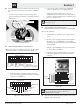
EN Section 1 The following dip switch settings pertain to AutoDome Versions 5.00 and newer. Switch # Function Position 1 RESERVED 2 Serial Mode Selection 3 RESERVED 4 Low Pressure Detection 1.5 To avoid confusion during installation, write the camera address on masking tape and stick it to the dome, as shown in PHOTO 1E. Selection The dome is now ready to be installed, using an appropriate AutoDome mount.
EN Section 1 b. Connect Video (BNC) cable and the CONTROL connector. Tighten screws on control connector. Attach the installation-assist cable* to the eyehook on the top of the dome, and close the safety cable (see PHOTO 1F). 1.6 c. When using Biphase, and the dome is in a star configuration (or is the last dome on a daisy chain), it requires a 110 Ω terminating resistor (included) across pin 8 (C+) and pin 9 (C–). * A cable (user-provided) is recommended for safety purposes when pipe mounting.
EN Section 1 Lift the AutoDome into the Pendant Arm and twist until the notch on the AutoDome is aligned with the notch on the SIDE of the pendant arm. ALIGN NOTCHES ROTATE Photo 1I Installed AutoDome Photo 1G Align notches 1.10 Tighten the two screws on the top of the pendant arm until snug. Photo 1H Tighten screws Some models require a slotted screw instead of an Allen screw. Apply power to the AutoDome. 1.11 If using the FastAddress feature, see SECTION 3 for additional information.
EN Section 2 If using RS-232/RS-485 Communications: SECTION 2 The unit is shipped with the RS-232/RS-485 Baud Rate set to 9600. This rate can be changed via the COMMUNICATIONS SETUP menu (see SECTION 6). In-ceiling AutoDome Installation Instructions 2.1 The following settings pertain to AutoDome versions 5.00 and newer: Before installing this unit, install and wire the In-ceiling Backbox (LTC 7490), following the instructions provided with that unit. Carefully remove the AutoDome from the box.
EN 2.3 Section 2 Attach the dome window to the camera module, aligning the blue LOCK labels. 2.6 While grasping the unit by the dome window, insert the camera module completely into the backbox. Snap the dome cover into position by pressing gently on the dome 90° from the blue labels. 90° RED DOTS FACING EACH OTHER BLUE LABEL Photo 2C Attach dome window 2.4 Photo 2F Insert camera module 90° 2.
EN Section 3 SECTION 3 FastAddress The FastAddress feature allows the AutoDome’s cameras to be addressed (or the address may be changed) via a keyboard and on-screen menus instead of using the switch address (thumbwheel). If FastAddress is not used, the camera’s address defaults to the address indicated by the thumbwheel switches. Conversely, if FastAddress has been programmed, the thumbwheel switches are ignored.
EN c. There is a visual confirmation that the address was cleared. Use ON-997-ENTER to check/confirm camera addresses. For example, if referring to Camera 3, press CAMERA-3-ENTER, then ON-997-ENTER. This causes all cameras to briefly display their addresses. FastAddress is stored to nonvolatile memory, thus will not change if power is removed or factory defaults are restored (SET-899-ENTER).
EN Section 5 TO CREATE A MASK: SECTION 5 1. First, use the joystick to maneuver to the area to be masked, then zoom in so that this area is between 25% to 50% of the total screen. 2. Press ON-87-ENTER to enter the menu (as shown in FIGURE 5A). Use the joystick to scroll through the list of masks until the desired mask is highlighted. Press Focus+ to edit this mask. 3. If desired, use the joystick to adjust the area to be masked.
EN 6. Press FOCUS again to continue. The AutoDome now adjusts its zoom position and allows fine-tuning of the mask coverage by using the joystick. FIGURE 5E shows a sample mask. Section 6 3. Use the joystick to move down to the Communication Setup menu and press FOCUS on the controller/keyboard. Figure 6B Communication Setup Figure 5E Adjusts Mask 7. When finished fine-tuning the mask, press either IRIS button to exit the menu and save the current mask.
EN SECTION 7 ALARMS 7.1 Inputs There are four (4) Alarm Inputs that may be activated by a dry contact input closure. The alarm conditions must be present for greater than 200 ms to be recognized as a valid alarm. Each alarm input may be individually programmed for the type and desired Action to occur when an alarm is received (as shown in FIGURE 7A). The choices available are listed in FIGURE 12F in the back of this manual, and are explained in the Advanced Menu, SECTION 12.
EN Section 7 When the pressure alarm is acknowledged using OFF-65-ENTER, the flashing display will stop, but the letter "P" will appear in the top right-hand corner of the monitor (PHOTO 7D). This AutoDome will continue to display this warning until the low-pressure problem has been corrected. Low Pressure Photo 7D Low Pressure Alarm continued 7.3 Alarm Relay Output The alarm relay output may be activated either manually, or triggered when an Alarm occurs.
EN SECTION 8 AutoTrack WHAT IS AutoTrack? The AutoTrack feature is a motion detector, which takes over PTZ control of the Dome. The user always has the ability to manually override by simply moving the joystick. It is sensitive to motion of all kinds, and should only be used in the same applications that a standard motion detector would be; anywhere there is little or no motion expected.
EN SECTION 9 PELCO PROTOCOL MODE 9.1 Description The Pelco Protocol Mode provides support for Pelco-P and Pelco-D protocols, and is incorporated in AutoDome firmware version 5.31 and higher. It features Auto Baud Detection which automatically detects and adjusts the AutoDome protocol and baud rate to match the controller’s. 9.2 Hardware Configuration 9.3 RS-485 Setup To use the Pelco Protocol Mode, the AutoDome must be configured for RS-485 operation. 1. 2. 3. Section 9 9.
EN Section 9 Bosch Menu… (Locked) Accesses the full AutoDome configuration menu and all AutoDome settings. Command Lock: (Locked) Allows/Disallows (ON/OFF) locked commands to be accessed. Edit Password: (Locked) Sets or displays password. See Auto Dome Security, SECTION 4 for details. (Must enter password to unlock menu even if set to 0000 or 9999.) FastAddress… (Locked) Sets/changes the dome address using the keyboard and on-screen menus.
EN 9.12 Special Considerations Refer to the controller’s user manual To get the best results with using a specific feature, refer to the Pelco controller’s user manual. Auto Baud Detection Feature Baud rate and protocol are automatically detected and adjusted by AutoDome whenever the controller starts transmitting. No manual adjustments are required. Because of the slow command repeat rate of the DX8000, Auto Baud Detection is slow.
EN Section 10 SECTION 10 MAINTENANCE/COMPONENT REPLACEMENT No special maintenance is required. Occasionally, dust may accumulate inside the housing and coat the transparent dome/trim ring. In this case, power the unit off and remove the dome so that it is away from the camera. While using proper eye protection, clean the dome with clean compressed air from a spray can and microwave-safe paper towels, then reseat the dome.
EN Section 11 SECTION 11 TROUBLESHOOTING GUIDE Problem Solution NO VIDEO • Ensure that the AutoDome is powered, and all cables are properly connected. • Ensure that the address is properly set. • Ensure that the biphase or RS-232 is connected. • Ensure that other cameras can be controlled; if not, check the control system. • Ensure that the address is set. If an address is set to 0000, it responds to commands for any address. • Ensure that GAIN CONTROL is set to AUTO (ON-43-ENTER).
EN Section 11 Problem Solution DAY/NIGHT CAMERA DOES NOT AUTOMATICALLY SWITCH WHEN IMAGE IS DARK • Set GAIN CONTROL to AUTO to enable this feature. • If the lower housing is equipped with a desiccant bag, it may need to be replaced (Bosch part #303 3804 003).
EN Section 12 SECTION 12 AUTODOME LOCKED COMMANDS CAMERA PTZ GENERAL SETUP Access to the AutoDome may be password-protected. See SECTION 4, AutoDome Security for details. To use Locked Commands, first unlock the AutoDome via OFF-90-ENTER. All locked settings, except FastAddress, can then be changed via ON-46-ENTER. Disallow these commands via ON-90-ENTER. Commands Keystrokes Description FastAddress On-999-Enter Sets/changes the dome address using the keyboard and on-screen menus.
EN Section 13 SECTION 13 ADVANCED MENU Main Menu Depending on the AutoDome password security set for your system, a password may be required to access the ADVANCED MENU. This enhanced software makes programming and customizing the AutoDome easy. All settings are editable via the Main Menu. Press ON-46-ENTER to enter the Main Menu. If no menu is displayed, the system may be locked. To unlock the AutoDome, press OFF-90-ENTER, and follow the on-screen commands to edit the settings.
EN Section 13 NOTE: The following four (4) CAMERA SETUP options pertain to Day/Night models only, and will not appear on the screen otherwise. Night Mode – Selects night mode (B/W) operation (Day/Night models only). Choices: . . . . . . . . . . . . . .On, Off, Auto. Night Mode Threshold – Adjusts the level of light at which the camera automatically switches to night mode (B/W) operation (Day/Night models only). Choices: . . . . . . . . . . . . . .Sliding Scale from 10 to 55 (in increments of five).
EN Section 13 PTZ SETUP (See FIGURE 13C for the PTZ SETUP menu hierarchy). Autopan Speed – Adjusts speed of the camera during Auto Pan/ Auto Scan. The Factory Default setting is 30°/sec. Choices: . . . . . . . . . . . . . .Sliding Scale from 1°/sec to 60°/sec. Tour Period – Changes dwell time between Presets during a Preset Tour. The Factory Default setting is five sec. Choices: . . . . . . . . . . . . . .Sliding Scale from 3 sec to 10 min.
EN Section 13 COMMUNICATION SETUP (See FIGURE 13E for COMMUNICATION SETUP hierarchy). Baud Rate – Controls baud rate for AutoDome communication in the Normal mode. Factory Default is 9600. Choices: . . . . . . . . . . . . .9600*, 19200, 38400, 57600. Bilinx - Enables/Disables the Bilinx communications directly through the coax. Factory Default is ON. Choices: ..............On*, Off. Restore Defaults – Restores ALL choices for this submenu ONLY, back to the Factory Defaults. Choices: . . . . . . . . . . .
EN Section 13 Sliding Scale 359° –0° *default = 0 Sliding Scale 1 sec 1/10,000 sec Auto Slow Shutter WHITE BALANCE SHUTTER NIGHT MODE Sliding Scale 10 55 NIGHT MODE THRESHOLD On *Off NIGHT MODE COLOR **Day/Night Settings On Off *Auto Off GAIN CONTROL CAMERA SETUP *Auto Sliding Scale 1 6 *default = 4 MAX GAIN LEVEL Sliding Scale – (soft) + (sharp) *default = 6 (on scale of ~16) SHARPNESS Crystal SYNCH MODE QUICKSET MODE On *Off Extended Auto WB *Automatic WB Indoor WB Outdoor WB One Pus
EN Section 13 *Off Scene 1 Prev Aux INACTIVITY AUTOPAN SPEED Sliding Scale 3 sec 10 min *default = 2 min INACTIVITY PERIOD *On Off *On Off AUTOPIVOT **AUTOTRACK COMMS *3.6 m (12 ft) adjustable from 2.4 to 30.
EN Section 13 *Off INPUT 1 INPUT 2 INPUT 3 ***INPUT 4 Input N.O. (Normally Open) N.C.
EN Appendix A APPENDIX A Power Wiring Guide AutoDome Power Wiring Connections Refer to the following diagram to ensure proper wiring of the AutoDome. If using the ENV-PSU for power, use the THREE WIRE POWER distances identified below. WARNING: Failure to correctly wire the power to the EnviroDome could result in heater malfunction. NOTE: If using the ENV-PSU with the AutoTracker option, the RS-232 connections (RXD, TXD, GND) must be used. The maximum distance for RS-232 communications is 50 ft.
EN Appendix B APPENDIX B Gasket Installation (to meet IP66/NEMA 4X, Dust-tight and Powerful Jetting) Install Gasket with Lip on Top.
EN AutoDome® and EnviroDome® Indoor Pendant In-ceiling Model User Manual Version 5.3 EN NOTE: Remove this User Manual and supply to user.
EN ON-SCREEN PROGRAMMING The AutoDome software offers user-friendly, on-screen programming. A few common commands are shown below. Additional commands are listed at the end of this manual. Saving a scene (Preset) The AutoDome allows up to 99 scenes to be saved and recalled instantly. A saved scene is called a Preset. When a Preset is saved, the position, zoom, and most camera settings are stored.
EN User Manual Record/Playback Tours Two independent macros (series of commands) can be recorded; A & B. These macros can be several hours in duration, although tours involving constant commands only last minutes. While recording, the on-screen display indicates remaining memory (see FIGURE 5). To begin recording on A, move the camera to the desired starting point and type ON-100-ENTER. The AutoDome now records all camera activities, until the recording is ended by OFF-100-ENTER.
EN User Manual Commands AUTODOME USER COMMANDS PRESET PTZ UNLOCKED COMMANDS Commands Scan AutoPan Preset Menu Preset Tour Preset Tour Period Preset Save Preset Call Edit Preset Title Edit Preset Tour ALARM Modify Preset Tour Alarm Clear/ Relay Output Record A SETUP RECORD Record B Continuous Playback A Playback A Continuous Playback B Playback B Scan+Auto Pan Speed Backlight Compensation View Factory Settings Software Version Night Mode Day/Night Menu AutoTrack Keystrokes ON/OFF-1-ENTER ON/OFF-2-
Americas Bosch Security Systems 130 Perinton Parkway Fairport, New York, 14450, USA Phone: +1 (585) 223 4060 Fax: +1 (585) 223 9180 E-mail: security.sales@us.bosch.com www.boschsecurity.us Europe, Middle East, Africa Bosch Security Systems B.V. P.O. Box 80002 5600 JB Eindhoven, The Netherlands E-mail: ema.securitysystems@bosch.com http://www.boschsecurity.com © 2005 Bosch Security Systems GmbH 3935 890 43816 05-07 | Updated February 15, 2005 | Data subject to change without notice.