EVI-12, EVI-15 and EVI-28 Loudspeaker Systems Applications Guide
In a nutshell, here are the major advantages of the new EVI systems: Welcome to the world of Vari Intense® horn technology from Electro-Voice.
Installation procedures for any conventional loudspeaker are fairly well-defined and easy to understand: find an appropriate hanging height and position that affords a clear path to the listening area (such as above the center of a stage or above the lectern in a church), and aim the loudspeaker towards the center or just to the rear of center of the room. With this method you hope to cover the majority of the room with fairly consistent sound, but the mid and high frequencies never seem to fill perfectly.
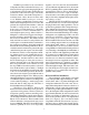
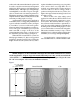
the same mounting height of 18 feet, but with the front of the enclosure tilted up by approximately 10° (see Figure 2), the total floorplan now encompassed the same 36 foot width, but at least 64 feet in length, an additional 10+ feet of extension. Of course, the front row position has moved back about 5 feet with the change in angle as shown, but this is easy to account for when initially positioning the system (and is exactly what happens if you take a conventional system and change the angle).
Q vs. Intelligibility: The “Q” of a system is a good measure of the system’s directivity, and in some ways a good measure of whether the system’s in-room response will be consistent across the frequency range. A typical 12-inch two-way system with a 60o x 40o horn will maintain a fairly constant Q from 16-30 or 12-15 dB (normally about 26, or 14dB) from 3,000–20,000 Hz, and a 90o x 40o a Q of 13-15 (11-12dB). Very-high-directivity horns such as a 40o x 20o will have an average Q in the range of 45 (16.
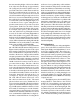
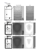
is that 3dB of long-throw SPL and 1.5-2dB of sidefill level has been lost. A higher resolution data file is needed to provide a “real world realistic” simulation. Figure 5 shows the raw 2° polar data with the averaged 10° data superimposed. Also shown are floorplans from our 2° modeler, DCSO, the 5degree AcoustaCADD and 10-degree EASE. By comparing the 2°, 5° and 10° resolution you can easily see the apparent loss in direct-field SPL.
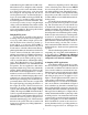
replace a distributed system along a very long, fairly wide corridor where very high SPLs are not required on a continuous basis (such as an airport concourse with 15 to 20 foot ceilings, where a speaker would be placed about every 75 feet). See Figure 10 for approximate mounting locations and floorplan coverage. These are but a few of the widely varied applications where the new EVI-12, EVI-15 and EVI-28 systems will easily outperform a conventional system.
Figure 2 EVI SYSTEM MOUNTED AT 18’ HEIGHT AND +10° AIMING ANGLE TILTED BACK FROM FLOOR Direct Field SPL C50 Figure 3 CONVENTIONAL 60X40 SYSTEM MOUNTED AT 18’ HEIGHT AND AIMED ABOUT 30° DOWN Direct Field SPL C50 CONVENTIONAL 60X40 SYSTEM MOUNTED AT 18’ HEIGHT AND AIMED ABOUT 25° DOWN Direct Field SPL C50 7
Figure 4 Direct Field SPL Figure 5 Horizontal Polar R aw S moothed AcoustaCADDTM Direct Field SPL Vertical Polar Raw S moothed EASETM Direct Field SPL DCSO Direct Field SPL 8
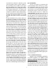
Figure 6 EVI SYSTEM MOUNTED AT 20’ HEIGHT AND 8° AIMING ANGLE Direct Field SPL C50 9
Figure 7 EVI SYSTEM MOUNTED AT 18’ HEIGHT AND -10° AIMING ANGLE EVI SYSTEM MOUNTED AT 22’ HEIGHT AND -10° AIMING ANGLE Direct Field SPL C50 10
Figure 8 EVI SYSTEM MOUNTED BACK-TO-BACK AT 30’ HEIGHT AND +5° AIMING ANGLE Direct Field SPL C50 11
Figure 9 EVI SYSTEM MOUNTED AT 25’ HEIGHT AND 15° AIMING ANGLE Direct Field SPL C50 12
Figure 10 2 EVI SYSTEM MOUNTED BACK-TO-BACK AT 40’ HEIGHT AND +10° AIMING ANGLE C50 Direct Field SPL 13
Figure 11 Figure 12 Figure 14 Figure 13 BOLTS AND CABLING/CHAINS MUST BE RATED FOR OVERHEAD LIFTING (NOT SUPPLIED) BOLTS AND CABLING/CHAINS MUST BE RATED FOR OVERHEAD LIFTING (SEE TEXT) 3/8-16 FORGED SHOULDER EYEBOLT (SUPPLIED) WITH PULL-UP STRAP PULL-UP STRAP ATTACHED TO 3/8-16 FORGED SHOULDER EYEBOLT (SEE TEXT) Figure 15 600 Cecil Street, Buchanan, MI 49107 800/234-6831, 616/695-6831, 616/695-1304 Fax ©Telex Communications, Inc. 1998 • Litho in U.S.A.