
Installation manual


Header connection
6 720 613 057 (2006/04)
30
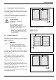
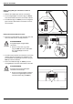
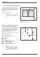
8.2 Venting through air vent (accessory) on roof
If you intend to vent the solar heating system with an au-
tomatic air-vent valve (accessory) at the highest point of
the system, run the flow line rising to the air-vent valve
(Fig. 34, Item 2) and the return line rising to the collector
array (Fig. 34).
Avoid frequent changes in direction.
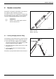
Function of the weather protection cap and weather
protection cap on the automatic air-vent valve
The solar heating system is vented through the opened
weather protection cap. When in operation, the weather
protection cap (Fig. 35, Item 1) must always be posi-
tioned over the weather protection cap to prevent mois-
ture entering the solar heating system through the
opened weather protection cap.
Open the air-vent valve by unscrewing the weather pro-
tection cap one full revolution.
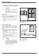
Universal air-vent set (Fig. 35):
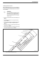
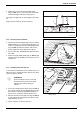
Fig. 34 View – air pot with vent valve for flow connection
Item 1: Collector sensor
Item 2: Automatic air-vent valve on roof
63043966.20-1.SD
63043966.20-1.SD
2
1
i
User note:
For each change of direction downwards
and each new rise, install an additional air
vent.
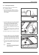
Fig. 35 Universal air-vent set
63043966.21-2.SD
63043966.21-2.SD
2
1
3
4
5
8
9
10
6
11
7
Item 1: Weather protection cap (weather protection
cap)
1 ×
Item 2: Automatic air vent 1 ×
Item 3: Ball valve 1 ×
Item 4: Gasket 1 ×
Item 5: Vent pot 1 ×
Item 6: Double threaded fitting threaded fitting
with O-ring
1 ×
Item 7: Threaded fitting R¾ (not required here) 1 ×
Item 8: Union nut (not required here) 2 ×
Item 9: Gasket (not required here) 1 ×
Item 10: Large diameter washer (not required here) 1 ×
Item 11: Clamping disc (not required here) 1 ×
i
User note:
The air vent set is designed for fitting the
vent directly to the collector or under the
roof. However with in-roof collectors the
airvent must be fitted under the roof.