Camera Browser Interface 2000 family en Software manual
Camera Browser Interface Table of Contents | en 3 Table of Contents 1 Browser connection 10 1.1 System requirements 10 1.2 Establishing the connection 11 1.2.1 Password protection in camera 11 1.3 Protected network 11 2 System Overview 12 2.1 Livepage 12 2.2 Recordings 12 2.3 Settings 12 3 Operation via the browser 13 3.1 Livepage 13 3.1.1 Image selection 13 3.1.2 Status icons 14 3.1.3 Cameras with PTZ control 15 3.1.4 View Control ROI 16 3.1.
en | Table of Contents Camera Browser Interface 5 Basic Mode 26 5.1 Device Access 26 5.1.1 Naming 26 5.1.2 Password 26 5.2 Date/Time 28 5.3 Network 29 5.4 Encoder 30 5.5 Audio 30 5.6 Recording 30 5.7 System Overview 30 6 Advanced General Settings 31 6.1 Identification 31 6.1.1 Naming 31 6.1.2 ID 31 6.1.3 iSCSI Initiator extension 31 6.2 Password 32 6.2.1 Password 32 6.2.2 Confirm password 32 6.3 Date/Time 33 6.3.1 Date format 33 6.3.
Camera Browser Interface Table of Contents | en 5 7.1.2 Company logo 37 7.1.3 Device logo 37 7.1.4 Show VCA metadata 37 7.1.5 Show VCA trajectories 37 7.1.6 Show overlay icons 38 7.1.7 Select video player 38 7.1.8 JPEG size, interval and quality 38 7.2 LIVEPAGE Functions 39 7.2.1 Transmit audio 39 7.2.2 Lease time [s] 39 7.2.3 Show event log 39 7.2.4 Show system log 39 7.2.5 Allow snapshots 39 7.2.6 Allow local recording 40 7.2.7 I-frames-only stream 40 7.2.
en | Table of Contents Camera Browser Interface 9 Encoder Settings 47 9.1 Encoder Profile 48 9.1.1 Pre-defined HD profiles 48 9.1.2 Changing a profile 48 9.1.3 Profile name 49 9.1.4 Target bit rate 49 9.1.5 Maximum bit rate 49 9.1.6 Encoding interval 49 9.1.7 Standard definition video resolution 49 9.1.8 Expert Settings 49 9.1.9 Default 51 9.2 Encoder Streams 52 9.2.1 H.264 settings 52 9.2.2 JPEG stream 53 9.3 Encoder Regions 54 9.3.
Camera Browser Interface Table of Contents | en 7 11 Alarm 66 11.1 Alarm Connections 66 11.1.1 Connect on alarm 66 11.1.2 Number of destination IP address 66 11.1.3 Destination IP address 66 11.1.4 Destination password 66 11.1.5 Video transmission 67 11.1.6 Stream 67 11.1.7 Remote port 67 11.1.8 Video output 67 11.1.9 Decoder 67 11.1.10 SSL encryption 68 11.1.11 Auto-connect 68 11.1.12 Audio 68 11.2 Video Content Analyses (VCA) 69 11.3 Audio Alarm 70 11.3.
en | Table of Contents Camera Browser Interface 12.2.1 Aggregation time [s] 12.2.2 Analysis type 75 75 12.2.3 Motion detector 76 12.2.4 Tamper detection 77 12.3 VCA - Scheduled 81 12.3.1 Weekdays 81 12.3.2 Holidays 81 12.4 VCA - Event triggered 83 12.4.1 Trigger 83 12.4.2 Trigger active 83 12.4.3 Trigger inactive 83 12.4.4 Delay [s] 83 13 Network 84 13.1 Network Access 84 13.1.1 Automatic IP assignment 84 13.1.2 IP V4 address 84 13.1.
Camera Browser Interface Table of Contents | en 9 13.2.1 SNMP 13.2.2 1. SNMP host address / 2. SNMP host address 89 13.2.3 SNMP traps 89 13.2.4 Authentication (802.1x) 90 13.2.5 RTSP port 90 13.2.6 UPnP 90 13.2.7 TCP metadata input 90 13.2.8 Quality of service 90 13.2.9 Cloud-based services 91 13.3 Multicast 92 13.3.1 Enable 92 13.3.2 Multicast Address 92 13.3.3 Port 93 13.3.4 Streaming 93 13.3.5 Multicast packet TTL 93 13.4 Image Posting 94 13.4.
en | Browser connection 1 Camera Browser Interface Browser connection A computer with Microsoft Internet Explorer is used to receive live images from the camera, control the camera, and replay stored sequences. The camera is configured over the network using the browser. 1.
Camera Browser Interface 1.2 Browser connection | en 11 Establishing the connection The camera must have a valid IP address and a compatible subnet mask to operate on your network. By default, DHCP is pre-set at the factory to ON and so your DHCP server assigns an IP address. With no DHCP server the default address is 192.168.0.1 1. Start the Web browser. 2. Enter the IP address of the camera as the URL. 3. During initial installation, confirm any security questions that appear.
en | System Overview 2 Camera Browser Interface System Overview When a connection is established, the Livepage is initially displayed. The application title bar displays three items: LIVEPAGE, PLAYBACK, SETTINGS. Note: The PLAYBACK link is only visible if a storage medium has been configured for recording. (With VRM recording this option is not active.) 2.1 Livepage The LIVEPAGE is used to display the live video stream and control the camera. 2.
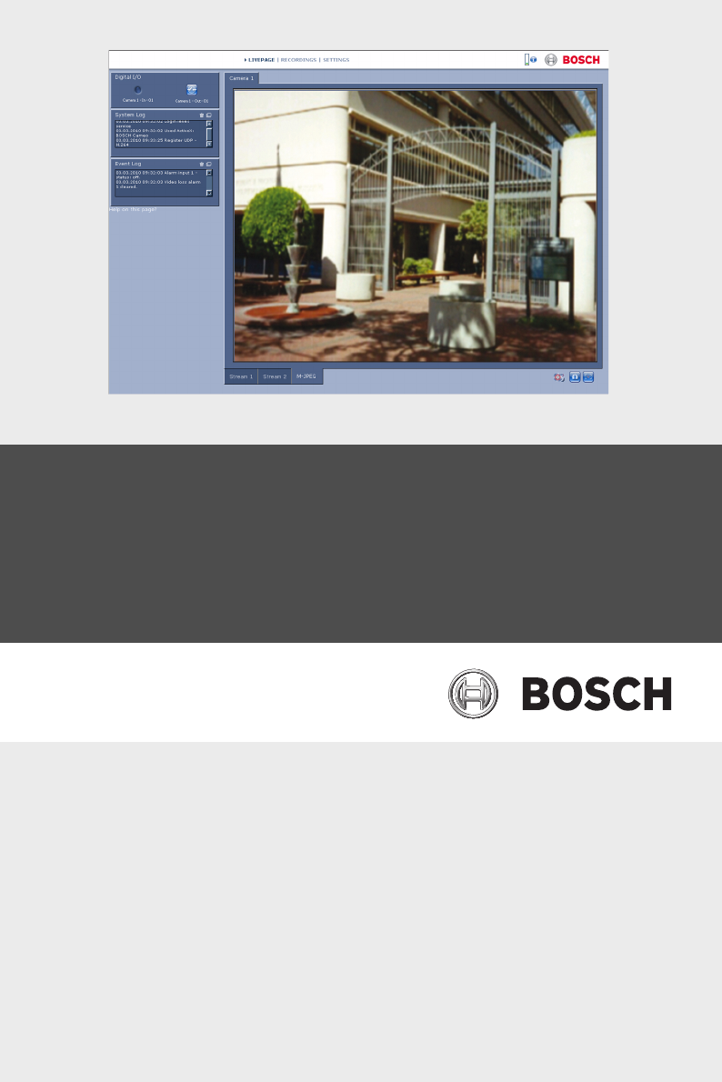
Camera Browser Interface Operation via the browser | en 3 Operation via the browser 3.1 Livepage 13 After the connection is established, the Livepage is initially displayed. It shows the live video image on the right of the browser window. Depending on the configuration, various text overlays may be visible on the live video image. Other information may also be shown next to the live video image. The items shown depend on the settings on the LIVEPAGE Functions page. Figure 3.1 3.1.
en | Operation via the browser 3.1.2 Camera Browser Interface Status icons Various overlays in the video image provide important status information. The overlays provide the following information: Decoding error The frame might show artefacts due to decoding errors. If other frames reference this frame, they might also show decoding errors but won’t be marked with the icon. Alarm flag Shown on a media item to indicate an alarm.
Camera Browser Interface Operation via the browser | en 15 Motion flag Indicates that motion is dectected. Storage discovery Indicates that recorded video is being retrieved. 3.1.3 Cameras with PTZ control For cameras where PTZ control is possible, the View Control panel is activated. Pan and tilt To control the pan and tilt of PTZ cameras: Click and hold the up or down arrows to tilt. Click and hold the left or right arrows to pan. Click and hold the center area to control both.
en | Operation via the browser Camera Browser Interface Pre-position To move the camera to a pre-position, click one of the buttons numbered one to six. To store the current position of the camera in a pre-position: 3.1.4 1. Position the camera. 2. Enter a pre-position number. 3. Click Set. View Control ROI (not for SD cameras) When the stream 2 encoder stream is set for Region of Interest (ROI), a specific type of View Control panel is activated. Refer to Section 9.2.1 H.
Camera Browser Interface Operation via the browser | en 17 Set positions To store the current view: 1. Select a region of interest. 2. Click Set. 3. Click a number. To display a pre-set region of interest, click one of the buttons numbered one to six. Intelligent Tracking For cameras with the ability to track movement, options for tracking objects within the region of interest are displayed in the Intelligent Tracking panel.
en | Operation via the browser 3.1.6 Camera Browser Interface System Log / Event Log The System Log field contains information about the operating status of the camera and the connection. Events such as the triggering or the end of alarms are shown in the Event Log field. To view, filter and save these messages to a file, click in the top right-hand corner. To clear the log, click in the top right-hand corner of the relevant field. 3.1.
Camera Browser Interface 3.1.9 Operation via the browser | en 19 Running recording program The hard drive icon below the camera images on the Livepage changes during an automatic recording. The icon lights up and displays a moving graphic to indicate a running recording. If no recording is taking place, a static icon is displayed. 3.1.
en | Operation via the browser 3.2 Camera Browser Interface Playback page Click PLAYBACK to access the Playback page from the Livepage or Settings page. The Playback link is only visible if a direct iSCSI or SD card has been configured for recording. (With VRM recording this option is not active.) A collapsible panel on the left of the display has four tabs: – Track list – Export – Search – Search results Select Recording 1 or 2 from the drop-down menu at the top of the window. 3.2.
Camera Browser Interface 3.2.2 Operation via the browser | en 21 Exporting tracks 1. Select a track in the track list. 2. Click the export tab. 3. The start and stop time are filled-in for the selected track. If required, change the times. 4. Select a target. 5. Select the original or a condensed speed. 6. Click the save icon . Note: The target server address is set on the Network/Accounts page. 3.2.3 Searching for tracks 1. Click the search tab. 2.
en | Operation via the browser 3.2.4 Camera Browser Interface Controlling playback Time bar The time bar below the video image allows quick orientation. The time interval associated with the sequence is displayed in the bar in gray. A green arrow above the bar indicates the position of the image currently being played back within the sequence. The time bar offers various options for navigation in and between sequences. – Change the time interval displayed by clicking the plus or minus icons.
Camera Browser Interface Operation via the browser | en 23 Jump to start of active sequence or to previous sequence Jump to start of the next video sequence in the list Bookmarks You can set markers in a sequence and jump to these directly. These bookmarks are indicated as small yellow arrows above the time interval.
en | Settings Overview Camera Browser Interface 4 Settings Overview 4.1 Configuration Menu The settings page provides access to the configuration menu which contains all the unit's parameters arranged in groups. There are two options for configuring the unit or checking the current settings: – Basic Mode – Advanced Mode In Basic Mode the most important parameters are arranged in seven groups.
Camera Browser Interface 4.2 Settings Overview | en 25 Settings Navigation To view the current settings: 1. Click the Basic Mode menu or the Advanced Mode menu to expand it. 2. For the Advanced Mode menu, click a menu sub-heading to expand it. 3. Click a sub-menu. The corresponding page is opened. Making Changes You can change the settings by entering new values or by selecting a predefined value from a list field. Note: When entering names do not use any special characters, for example &.
en | Basic Mode Camera Browser Interface 5 Basic Mode 5.1 Device Access 5.1.1 Naming Enter a unique name to assist in identification. This name simplifies the management of multiple devices in more extensive systems. The name is used for remote identification, for example, in the event of an alarm. Choose a name that makes it as easy as possible to identify the location unambiguously. 5.1.2 Password A password prevents unauthorized access to the device.
Camera Browser Interface Basic Mode | en 27 Password Define or change a separate password for each level. Enter the password (19 characters maximum) for the selected level. Confirm password Re-enter the new password to ensure that there are no typing mistakes. The new password is only saved after clicking Set. Therefore, click Set immediately after entering and confirming the password, even if assigning a password at another level. Bosch Security Systems Software manual AM18-Q0635 | v5.8 | 2013.
en | Basic Mode 5.2 Camera Browser Interface Date/Time Device date, time and zone If there are multiple devices operating in the system or network, it is important to synchronize their internal clocks. For example, it is only possible to identify and correctly evaluate simultaneous recordings when all devices are operating on the same time. Device time, date and time zone are shown. Click Sync to PC to apply the system time from your computer to the device.
Camera Browser Interface 5.3 Basic Mode | en 29 Network Use the settings on this page to integrate the device into a network. Some changes only take effect after a reboot. In this case, the Set button changes to Set and Reboot. 1. Make the desired changes. 2. Click Set and Reboot. – The device is rebooted and the changed settings are activated. If the IP address, subnet mask, or gateway address is changed, then the device is only accessible under the new addresses after the reboot.
en | Basic Mode 5.4 Camera Browser Interface Encoder Select a profile for encoding the video signal on stream 1 (this is not a selection of the recording profile). Pre-programmed profiles are available that give priority to different parameters and they should be selected based on your operating environment. When a profile is selected, its details are displayed. 5.5 Audio (only for cameras with microphones) Switch the camera audio On or Off. 5.
Camera Browser Interface Advanced General Settings | en 6 Advanced General Settings 6.1 Identification 6.1.1 Naming 31 Assign a unique name to assist in identification. This name simplifies the management of multiple devices in more extensive systems. The name is used for remote identification, for example, in the event of an alarm. Choose a name that makes it as easy as possible to identify the location unambiguously. 6.1.
en | Advanced General Settings 6.2 Camera Browser Interface Password A password prevents unauthorized access to the device. The device has three authorization levels: service, user, and live. – service is the highest authorization level. Entering the correct password gives access to all the functions of the camera and allows all configuration settings to be changed. – user is the middle authorization level.
Camera Browser Interface 6.3 Date/Time 6.3.1 Date format Advanced General Settings | en 33 Select the required date format. 6.3.2 Device date / Device time If there are multiple devices operating in your system or network, it is important to synchronize their internal clocks. For example, it is only possible to identify and correctly evaluate simultaneous recordings when all devices are operating on the same time. 1. Enter the current date.
en | Advanced General Settings Camera Browser Interface First, check the time zone setting. If it is not correct, select the appropriate time zone for the system: 1. Click Set. 2. Click Details. A new window opens showing an empty table. 3. Click Generate to fill the table with the preset values from the camera. 4. Select the region or the city which is closest to the system's location from the list box below the table. 5. Click one of the entries in the table to make changes. The 6.
Camera Browser Interface 6.4 Advanced General Settings | en 35 Display Stamping Various overlays or stamps in the video image provide important supplementary information. These overlays can be enabled individually and arranged on the image in a clear manner. 6.4.1 Camera name stamping Select the position of the camera name overlay in the dropdown box. It can be displayed at the Top, at the Bottom, or at a position of choice using the Custom option, or it can be set to Off for no overlay information.
en | Advanced General Settings 6.4.5 Camera Browser Interface Alarm message Enter the message to be displayed on the image in the event of an alarm. The maximum text length is 31 characters. 6.4.6 Video watermarking Select On in the drop-down box for the transmitted video images to be watermarked. After activation, all images are marked with an icon. The icon indicates if the sequence (live or saved) has been manipulated. AM18-Q0635 | v5.8 | 2013.
Camera Browser Interface Web Interface | en 7 Web Interface 7.1 Appearance 37 You can adapt the appearance of the web interface and change the website language to meet your requirements. GIF or JPEG images can be used to replace the company and device logos. The image can be stored on a local computer, a local network, or at an Internet address. The file paths must correspond to the access mode, for example: – – C:\Images\Logo.gif for access to local files, or http://www.myhostname.com/images/logo.
en | Web Interface 7.1.6 Camera Browser Interface Show overlay icons When selected, the camera status icons are displayed as an overlay on the video images. 7.1.7 Select video player Select the player to be used for live mode viewing. 7.1.8 JPEG size, interval and quality Select the size, update interval and quality of the M-JPEG image displayed on the livepage. The highest quality is 1. AM18-Q0635 | v5.8 | 2013.
Camera Browser Interface 7.2 Web Interface | en 39 LIVEPAGE Functions You can adapt the Livepage functions to meet your requirements. Choose from a variety of different options for displaying information and controls. 1. Mark the checkboxes for the functions to be shown on the Livepage. The selected elements are checked. 2. Look at the Livepage to see if the desired items are shown. Note: Only those checkboxes that are relevant for your type of camera are shown. 7.2.
en | Web Interface 7.2.6 Camera Browser Interface Allow local recording Specify whether the icon for saving video sequences locally should be displayed below the live image. Video sequences can only be saved if this icon is visible. 7.2.7 I-frames-only stream Select to display an additional tab on the Livepage where only Iframes can be viewed. (Ensure that I-frame quality is not set to Auto or no updates will occur.) 7.2.
Camera Browser Interface 7.3 7.3.1 Web Interface | en 41 Logging Save event log Select this option to save event messages in a text file on the local computer. This file can be viewed, edited, and printed with any text editor or standard office software. File for event log Enter the path for saving the event log here. If necessary, click Browse... to find a suitable folder. 7.3.2 Save system log Select this option to save system messages in a text file on the local computer.
en | Camera Camera Browser Interface 8 Camera 8.1 Installer Menu 8.1.1 Mirror image Select On to output a mirror image of the camera picture. 8.1.2 Flip image Select On to output an upside down camera image. 8.1.3 Main frequency and Operation environment Select 50 Hz or 60 Hz as the main frequency, and Indoor or Outdoor for the operation environment. 8.1.4 Exposure/frame rate – Auto exposure/frame rate: the camera automatically sets the framerate.
Camera Browser Interface 8.2 Camera | en 43 Picture Settings Contrast (0...255) Adjust the contrast with the slider from 0 to 255. Saturation (0...255) Adjust the color saturation with the slider from 0 to 255. Brightness (0...255) Adjust the brightness with the slider from 0 to 255. 8.2.1 White balance – Indoor: Allows the camera to continually adjust for optimal color reproduction in an indoor environment.
en | Camera Camera Browser Interface 8.3 Enhance 8.3.1 Sharpness level Adjusts the black level between -15 and +15. Zero position of slider corresponds to the factory default level. A low (negative) value makes the picture less sharp. Increasing sharpness brings out more detail. Extra sharpness can enhance the details of license plates, facial features and the edges of certain surfaces but can increase bandwidth requirements. AM18-Q0635 | v5.8 | 2013.
Camera Browser Interface 8.4 Camera | en 45 Encoder Settings The Encoder Profile, Encoder Streams, and Encoder Regions settings allow you to adapt the video data transmission characteristics for your operating environment (network structure, bandwidth, data structures). The camera simultaneously generates two H.264 video streams and an M-JPEG stream for transmission. An I-frame only stream is used for recording.
en | Camera 8.5 Camera Browser Interface Privacy Masks Four privacy mask areas can be defined. The activated masked areas are filled with the selected pattern in live view. 8.6 1. Select the pattern to be used for all masks. 2. Check the box of the mask you wish to activate. 3. Use the mouse to define the area for each of the masks. Audio Switch the audio On or Off. Adust the level with the slider. Select G.711, L16 or AAC* as the audio Recording format.
Camera Browser Interface 9 Encoder Settings | en 47 Encoder Settings The encoder settings determine the characteristics of the streams generated by the camera. The type of streams that can be generated for HD cameras are: – HD streams – SD streams – i-frame only streams for recording – M-JPEG streams The bit rates, the encoding interval, and the Group-of-Pictures (GoP) structure and quality, are defined and stored for 8 different profiles on the Encoder Profile page.
en | Encoder Settings 9.1 Camera Browser Interface Encoder Profile Profiles are rather complex and include a number of parameters that interact with one another, so it is generally best to use the pre-defined profiles. Only change a profile if completely familiar with all the configuration options. 9.1.1 Pre-defined HD profiles Eight definable profiles are available. The pre-defined profiles give priority to different parameters.
Camera Browser Interface 9.1.3 Encoder Settings | en 49 Profile name If required, enter a new name for the profile. 9.1.4 Target bit rate To optimize use of the bandwidth in the network, limit the data rate for the camera. The target data rate should be set according to the desired picture quality for typical scenes with no excessive motion.
en | Encoder Settings Camera Browser Interface GOP structure Select the structure you require for the Group of Pictures (GOP). Depending on whether you place greater priority on having the lowest possible delay (IP frames only) or using as little bandwidth possible, you choose IP, IBP or IBBP. Averaging period Select the appropriate averaging period as a means of stabilizing the long term bit rate. I-frame distance Use the slider to set the distance between I-frames to Auto or to between 3 and 60.
Camera Browser Interface 3. Encoder Settings | en 51 Set the value for I/P-frame delta QP to the lowest possible value. This is how to save bandwidth and memory in normal scenes. The image quality is retained even in the case of increased movement since the bandwidth is then filled up to the value that is entered under Maximum bit rate. Background delta QP Select the appropriate encoding quality level for a background region defined in Encoder Regions.
en | Encoder Settings Camera Browser Interface 9.2 Encoder Streams 9.2.1 H.264 settings Select H.264 Settings 1. Select a codec algorithm Property for stream 1 from the drop-down box. 2. Select a codec algorithm Property for stream 2 (the available choices depend on the algorithm selected for stream 1). 3. Select the Non-recording profile for each stream from the eight profiles that have been defined. – This profile is not used for recording.
Camera Browser Interface 9.2.2 Encoder Settings | en 53 JPEG stream Set the parmeters for the M-JPEG stream. – Select the Resolution. – Select the Max. frame rate in images per second (IPS). – The Picture quality slider allows adjustment of the M-JPEG image quality from Low to High. Note: The M-JPEG frame rate can vary depending on system loading. Bosch Security Systems Software manual AM18-Q0635 | v5.8 | 2013.
en | Encoder Settings Camera Browser Interface 9.3 Encoder Regions 9.3.1 Regions 1. Select one of the eight available regions from the dropdown box. 2. Use the mouse to define the area for that region by 3. Select the encoder quality to be used for the defined area. dragging the center or sides of the shaded window. (Object and background quality levels are defined on the Expert Settings section of the Encoder Profile page.) 4. If required, select another region and repeat steps 2 and 3. 5.
Camera Browser Interface 10 Recording | en 55 Recording Images can be recorded to an appropriately configured iSCSI system or, for cameras with SD slots, locally to an SD card. SD cards are the ideal solution for shorter storage times and temporary recordings. They can be used for local alarm recording or for Automatic Network Replenishment (ANR) to improve the overall reliability of video recording. For long-term authoritative images use an appropriately sized iSCSI system.
en | Recording 10.1 10.1.1 Camera Browser Interface Storage Management Device manager Check the Managed by VRM box to let an external Video Recording Manager (VRM) manage all recording. No further settings can be configured. Note: Activating or deactivating VRM causes the current storage settings to be lost; they can only be restored through reconfiguration. 10.1.2 Recording media Select a media tab to connect to the available storage media.
Camera Browser Interface Recording | en 57 Local Media An SD card can be used for local recording in cameras with an SD slot. If the SD card is password protected, enter the password into the Password field. The Storage overview field displays the local media. Note: SD card recording performance is highly dependent on the speed (class) and performance of the SD card. An SD card of Class 6 or higher is recommended. Bosch Security Systems Software manual AM18-Q0635 | v5.8 | 2013.
en | Recording 10.1.3 Camera Browser Interface Activating and configuring storage media Available media or iSCSI drives must be transferred to the Managed storage media list, activated, and configured for storage. Note: A iSCSI target storage device can only be associated with one user. If a target is being used by another user, ensure that the current user no longer needs the target before decoupling that user. 1.
Camera Browser Interface 1. Recording | en 59 Click a storage medium in the Managed storage media list to select it. 2. Click Remove below the list. The storage medium is deactivated and removed from the list. Bosch Security Systems Software manual AM18-Q0635 | v5.8 | 2013.
en | Recording 10.2 Camera Browser Interface Recording Profiles A recording profile contains the characteristics of the tracks that are used for recording. These characteristics can be defined for ten different profiles. The profiles can then be assigned to days or times of day on the Recording Scheduler page. Each profile is color-coded. The names of the profiles can be changed on the Recording Scheduler page. To configure a profile, click its tab to open its settings page.
Camera Browser Interface 10.2.1 Recording | en 61 Recording track selection Standard and alarm recording can be defined for the two recording tracks. You must first select the track before setting up the standard and alarm recording parameters. 1. Click the Recording 1 entry in the list. 2. Set up the standard and alarm recording parameters for track 1 as described below. 3. 4. Click the Recording 2 entry in the list.
en | Recording 10.2.3 Camera Browser Interface Alarm recording Select a period for the Pre-alarm time from the list box. Select a period for the Post-alarm time from the list box. Alarm stream Select the stream to be used for alarm recordings: – Stream 1 – Stream 2 – I-frames only Check the encoding interval and bit rates from profile: box and select an encoder profile to set the associated encoding interval for alarm recording. Check the Export to account box to send standard H.
Camera Browser Interface 10.4 Recording | en 63 Recording Scheduler The recording scheduler allows you to link the created recording profiles to the days and times at which the camera's images are to be recorded. Schedules can be defined for weekdays and for holidays. 10.4.1 Weekdays Assign as many time periods (in 15-minute intervals) as needed for any day of the week. Move the mouse cursor over the table — the time is displayed. 1. 2. Click the profile to be assigned in the Time periods box.
en | Recording Camera Browser Interface 3. Click OK. The selection is removed from the table and the 4. Repeat for any other dates to be deleted. window is closed. 10.4.3 Profile names Change the names of the recording profiles listed in the Time periods box. 10.4.4 1. Click a profile. 2. Click Rename. 3. Enter the new name and click Rename again. Activate recording After completing configuration, activate the recording schedule and start scheduled recording.
Camera Browser Interface 10.5 Recording | en 65 Recording Status Details of the recording status are displayed here for information. These settings cannot be changed. Bosch Security Systems Software manual AM18-Q0635 | v5.8 | 2013.
en | Alarm Camera Browser Interface 11 Alarm 11.1 Alarm Connections In the event of an alarm, the camera can automatically connect to a pre-defined IP address. The camera can contact up to ten IP addresses in the order listed until a connection is established. 11.1.1 Connect on alarm Select On so that the camera automatically connects to a predefined IP address in the event of an alarm. Select Follows input 1 so that the device maintains the connection for as long as an alarm exists. 11.1.
Camera Browser Interface Alarm | en 3. Enter the password in the Destination password field. 4. Set the user password of all the remote stations to be 67 accessed using this password. Setting destination 10 to the IP-address 0.0.0.0 overrides its function as the tenth address to try. 11.1.5 Video transmission If the device is operated behind a firewall, select TCP (HTTP port) as the transfer protocol. For use in a local network, select UDP.
en | Alarm 11.1.10 Camera Browser Interface SSL encryption SSL encryption protects data used for establishing a connection, such as the password. By selecting On, only encrypted ports are available for the Remote port parameter. SSL encryption must be activated and configured on both sides of a connection. The appropriate certificates must also have been uploaded. Configure and activate encryption for media data (video, metadata) on the Encryption page. 11.1.
Camera Browser Interface 11.2 Alarm | en 69 Video Content Analyses (VCA) The camera has integrated Video Content Analyses (VCA) which detects and analyze changes in the picture using image processing algorithms. Such changes can be due to movements in the camera's field of view. Detection of movement can be used to trigger an alarm and to transmit metadata. Various VCA configurations can be selected and adapted to your application, as required.
en | Alarm 11.3 Camera Browser Interface Audio Alarm (only for cameras with audio) Alarms can be generated based on audio signals. Configure signal strengths and frequency ranges so that false alarms, for example, machine noise or background noise, are avoided. Set up normal audio transmission before configuring the audio alarm. 11.3.1 Audio alarm Select On for the device to generate audio alarms. 11.3.
Camera Browser Interface 11.4 Alarm | en 71 Alarm E-Mail Alarm states can be documented by e-mail. The camera automatically sends an e-mail to a user-defined e-mail address. This makes it possible to notify a recipient who does not have a video receiver. 11.4.1 Send alarm e-mail Select On for the device to automatically send an alarm e-mail in the event of an alarm. 11.4.2 Mail server IP address Enter the IP address of a mail server that operates on the SMTP standard (Simple Mail Transfer Protocol).
en | Alarm 11.4.7 Camera Browser Interface Attach JPEG from camera Check the box to specify that JPEG images are sent from the camera. 11.4.8 Destination address Enter the e-mail address for alarm e-mails here. The maximum address length is 49 characters. 11.4.9 Sender address Enter a unique name for the e-mail sender, for example, the location of the device. This makes it easier to identify the origin of the e-mail. 11.4.10 Test e-mail Click Send Now to test the e-mail function.
Camera Browser Interface 11.5 Alarm | en 73 Alarm Task Editor Editing scripts on this page overwrites all settings and entries on the other alarm pages. This procedure cannot be reversed. To edit this page, you should have programming knowledge and be familiar with the information in the Alarm Task Script Language document and the English language. As an alternative to the alarm settings on the various alarm pages, enter the desired alarm functions in script form here.
en | Setting up VCA 12 Camera Browser Interface Setting up VCA Several VCA configurations are available. 12.1 – Off – Silent VCA – Profile #1 – Profile #2 – Scheduled – Event triggered VCA - Silent VCA In this configuration, metadata is created to facilitate searches of recordings, however, no alarm is triggered. In the VCA configuration drop-down list, select Silent VCA. No parameters can be changed for this selection. AM18-Q0635 | v5.8 | 2013.
Camera Browser Interface 12.2 Setting up VCA | en 75 VCA - Profiles Two profiles can be set up with different VCA configurations. 1. In the VCA configuration drop-down list, select profile 1 or 2 and enter the required settings. 2. If necessary, click Default to return all settings of the selected profile to its default values. To rename a profile: 1. To rename the file, click the icon to the right of the list field and enter the new profile name in the field. 2. Click the icon again.
en | Setting up VCA 12.2.3 Camera Browser Interface Motion detector Motion detection is available for the Motion+ analysis type. For the detector to function, the following conditions must be met: – Analysis must be activated. – At least one sensor field must be activated. – The individual parameters must be configured to suit the operating environment and the desired responses. – The sensitivity must be set to a value greater than zero. Note: Reflections of light (from glass surfaces, etc.
Camera Browser Interface Setting up VCA | en 77 Selecting the area Select the areas of the image to be monitored by the motion detector. The video image is subdivided into square sensor fields. Activate or deactivate each of these fields individually. To exclude particular regions of the camera's field of view from monitoring due to continuous movement (by a tree in the wind, for example), the relevant fields can be deactivated. 1. Click Select Area to configure the sensor fields. A new window opens.
en | Setting up VCA Camera Browser Interface the triggering condition still exists. If the original condition has been restored before this time interval elapses, the alarm is not triggered. This avoids false alarms triggered by short-term changes, for example, cleaning activities in the direct field of vision of the camera. Global change (slider) Set how large the global change in the video image must be for an alarm to be triggered.
Camera Browser Interface Setting up VCA | en 79 Reference check Save a reference image that can be continuously compared with the current video image. If the current video image in the marked areas differs from the reference image, an alarm is triggered. This detects tampering that would otherwise not be detected, for example, if the camera is turned. 1. Click Reference to save the currently visible video- image as a reference. 2.
en | Setting up VCA 1. Camera Browser Interface Click Select Area to configure the sensor fields. A new window opens. 2. If necessary, click Clear All first to clear the current selection (fields marked yellow). 3. Left-click the fields to be activated. Activated fields are marked yellow. 4. If necessary, click Select All to select the entire videoframe for monitoring. 5. Right-click any fields to deactivate. 6. Click OK to save the configuration. 7.
Camera Browser Interface 12.3 Setting up VCA | en 81 VCA - Scheduled A scheduled configuration allows you to link a VCA profile with the days and times at which the video content analysis is to be active. In the VCA configuration drop-down list, select Scheduled. Schedules can be defined for weekdays and for holidays. The current alarm status is displayed for information purposes. 12.3.1 Weekdays Link any number of 15-minute intervals with the VCA profiles for each day of the week.
en | Setting up VCA Camera Browser Interface Deleting Holidays Delete defined holidays at any time: 1. Click Delete. A new window opens. 2. Click the date to delete. 3. Click OK. The item is deleted from the table and the window closes. 4. The process must be repeated for deleting additional days. AM18-Q0635 | v5.8 | 2013.
Camera Browser Interface 12.4 Setting up VCA | en 83 VCA - Event triggered This configuration allows you to stipulate that the video content analysis is only to be activated when triggered by an event. In the VCA configuration drop-down list, select Event triggered. As long as no trigger is activated, the Silent MOTION+ configuration in which metadata is created is active; this metadata facilitates searches of recordings, but does not trigger an alarm.
en | Network Camera Browser Interface 13 Network 13.1 Network Access The settings on this page are used to integrate the device into a network. Some changes only take effect after a reboot. In this case Set changes to Set and Reboot. 1. Make the desired changes. 2. Click Set and Reboot. The device is rebooted and the changed settings are activated. If the IP address, subnet mask, or gateway address is changed, then the device is only available under the new addresses after the reboot. 13.1.
Camera Browser Interface 13.1.3 Network | en 85 IP V6 address IP address Enter the desired IP address for the camera. The IP address must be valid for the network. Prefix length Enter the appropriate prefix length for the set IP address. Gateway address For the device to establish a connection to a remote location in a different subnet, enter the IP address of the gateway here. Otherwise, this field can remain empty (0.0.0.0). 13.1.
en | Network 13.1.8 Camera Browser Interface HTTPS browser port To limit browser access to encrypted connections, choose an HTTPS port from the list. The standard HTTPS port is 443. Select the Off option to deactivate HTTPS ports and limit connections to unencrypted ports. The camera uses the TLS 1.0 protocol. Ensure that the browser has been configured to support this protocol. Also ensure that Java application support is activated (in the Java Plug-in Control Panel of the Windows Control Panel).
Camera Browser Interface 13.1.13 Network | en 87 iSCSI MSS [Byte] Specify a higher MSS value for a connection to the iSCSI system than for the other data traffic via the network. The potential value depends on the network structure. A higher value is only useful if the iSCSI system is located in the same subnet as the camera. 13.1.14 Network MTU [Byte] Specify a maximum value in bytes for the package size (including IP header) to optimize data transmission. 13.1.
en | Network Camera Browser Interface use this function when necessary and no more than once a day, to avoid the possibility of being blocked by the service provider. To transfer the IP address of the device, click the Register button. 13.1.21 Status The status of the DynDNS function is displayed here for information purposes; these settings cannot be changed. AM18-Q0635 | v5.8 | 2013.
Camera Browser Interface 13.2 Network | en 89 Advanced The settings on this page are used to set advanced settings the network. Some changes only take effect after a reboot. In this case Set changes to Set and Reboot. 1. Make the desired changes. 2. Click Set and Reboot. The device is rebooted and the changed settings are activated. 13.2.
en | Network 13.2.4 Camera Browser Interface Authentication (802.1x) To configure Radius server authentication, connect the camera directly to a computer using a network cable. If a Radius server controls access rights over the network, select On to activate authentication to communicate with the device. 1. Enter the user name that the Radius server uses for the 2. Enter the Password that the Radius server expects from camera in the Identity field. the camera. 13.2.
Camera Browser Interface Network | en 91 define a Post Alarm Time over which this priority is maintained. 13.2.9 Cloud-based services The User Mode determines how the camera communicates with the Bosch Cloud-based Security and Services. For more information about these sevices and their availability, visit: http://cloud.boschsecurity.com – Select Auto to allow the camera to poll the server a few times; if no contact is made it stops polling. – Select On to constantly poll the server.
en | Network 13.3 Camera Browser Interface Multicast The camera can enable multiple receivers to receive the video signal simultaneously. The stream is either duplicated and then distributed to multiple receivers (Multi-unicast), or it is sent as a single stream to the network, where it is simultaneously distributed to multiple receivers in a defined group (Multicast). Multicast operation requires a multicast-enabled network that uses UDP and the Internet Group Management protocol (IGMP V2).
Camera Browser Interface Network | en 93 Duplication of data places a heavy demand on the CPU and can lead to impairment of the image quality under certain circumstances. 13.3.3 Port Enter the port address for the stream here. 13.3.4 Streaming Click the checkbox to activate multicast streaming mode. An activated stream is marked with a check. (Streaming is typically not required for standard multicast operation.) 13.3.
en | Network 13.4 Camera Browser Interface Image Posting A target account must first be defined to use JPEG and Best faces posting and for the export of recordings. 13.4.1 JPEG Send individual JPEG images to a target account at specific intervals. JPEG resolution corresponds to the highest setting from the two data streams. Image size Select the size of the JPEG images that are to be sent from the camera. File name Select how file names are created for the individual images that are transmitted.
Camera Browser Interface 13.5 Network | en 95 Accounts Four separate accounts can be defined for posting and recording export. Type Select either FTP or Dropbox for the account type. Account name Enter an account name to be shown as the target name. IP address For an FTP server, enter the IP address. Login Enter your login name for the account server. Password Enter the password that gives access to the account server. Click Check to confirm that it is correct.
en | Network 13.6 Camera Browser Interface IP V4 filter To restrict the range of IP addresses within which you can actively connect to the device, fill-in an IP address and mask. Two ranges can be defined. Click Set and confirm to restrict access. If either of these ranges are set, no IP V6 addresses are allowed to actively connect to the device. The device itself may initiate a connection (for example, to send an alarm) outside the defined ranges if it is configured to do so. AM18-Q0635 | v5.
Camera Browser Interface 14 Service 14.1 Maintenance Service | en 97 CAUTION! Before starting a firmware update, make sure to select the correct upload file. Uploading the wrong files can result in the device no longer being addressable, requiring it to be replaced. Do not interrupt the firmware installation. Even changing to another page or closing the browser window leads to interruption. Interruption may lead to faulty coding of the Flash memory.
en | Service 3. Camera Browser Interface Click Upload to begin transferring the file to the device. The progress bar allows monitoring of the transfer. The new firmware is unpacked and the Flash memory is reprogrammed. The time remaining is shown by the message going to reset Reconnecting in ... seconds. When the upload is completed successfully, the device reboots automatically. If the operating status LED lights up red, the upload has failed and must be repeated.
Camera Browser Interface Service | en 99 Once all files have been successfully uploaded, the device must be rebooted. In the address field of the browser, enter /reset after the camera's IP address, for example: 192.168.0.10/reset The new SSL certificate is valid. 14.1.5 Maintenance log Download an internal maintenance log from the device to send it to Customer Service for support purposes. Click Download and select a storage location for the file. 14.1.
en | Service AM18-Q0635 | v5.8 | 2013.
Bosch Security Systems www.boschsecurity.