Networking Cards FPE-1000-NE | -NF | -NW en Installation Manual
FPE-1000-NE | -NF | -NW 1 3 Documentation Availability Note For additional documentation including documents in languages other than English, see this CD (shipped with the FPA-1000 Fire Panel). Para obtener documentación adicional, incluyendo los documentos en idiomas distintos del Inglés, vea este CD (incluido con la central de incendios FPA-1000). Para obter documentação adicional incluindo documentos em outros idiomas além do Inglês, consulte este CD (fornecido com o Painel de Incêndio FPA-1000).
F.01U.214.374 | 01 | 2012.08 FPE-1000-NE | -NF | -NW Bosch Security System, Inc.
Networking Cards Table of Contents | en 5 Table of Contents 1 Safety 6 1.1 General 6 1.2 Disclaimer 6 1.2.1 Disclaimer According to the GNU General Product Licence 6 1.2.2 Disclaimer According to the GNU Library General Product Licence 7 2 System Overview 8 3 Planning 9 3.1 General considerations 9 3.2 Ground Fault Detection 9 3.3 Port supervision 9 4 Installation 11 4.1 General considerations 11 4.2 Mounting 11 5 Connection 13 5.1 General considerations 13 5.
en | Safety Networking Cards 1 Safety 1.1 General DANGER! Fire panels are Life safety devices. Only trained personnel should install and program these panels! Any panel in a network can control all other panels in the network (e.g. silencing an alarm or resetting the system). Access to panels should be restricted to properly trained personnel. Use these instructions to install FPE-1000 Networking Cards in FPA-1000 Analog Addressable Fire Panels. 1.
Networking Cards Safety | en 7 OR A FAILURE OF THE PROGRAM TO OPERATE WITH ANY OTHER PROGRAMS), EVEN IF SUCH HOLDER OR OTHER PARTY HAS BEEN ADVISED OF THE POSSIBILITY OF SUCH DAMAGES. 1.2.2 Disclaimer According to the GNU Library General Product Licence NO WARRANTY BECAUSE THE LIBRARY IS LICENSED FREE OF CHARGE, THERE IS NO WARRANTY FOR THE LIBRARY, TO THE EXTENT PERMITTED BY APPLICABLE LAW.
en | System Overview 2 Networking Cards System Overview The FPA-1000 Analog Addressable Fire Panels are advanced analog addressable control panels for small to large facilities in residential, commercial or public building applications. Optional networking cards allow multiple panels to be interconnected into a networked system. The network acts as if it were a single panel for purposes of communication.
Networking Cards Planning | en 3 Planning 3.1 General considerations 9 If the panel is to be used in a networked system, be careful to plan properly before installing any panels.
en | Planning Networking Cards Browser-based Operation and Programming, Networking in the FPA-1000 Installation and Operation Guide. F.01U.214.374 | 01 | 2012.08 Installation Manual Bosch Security System, Inc.
Networking Cards Installation | en 4 Installation 4.1 General considerations 11 CAUTION! Electrostatic discharge! Ground yourself using a wrist strap or take other suitable actions. The FPA-1000 circuit boards have static-sensitive components that could become damaged. Run the ground wire to the enclosure before handling these circuit boards. Touch ground before unpacking and handling the circuit boards. This discharges any static electricity in your body.
en | Installation Networking Cards AC IN Fire Alarm Gas Alarm Power Supervisory Silenced Trouble DRILL @ RESET SILENCE ACK _ . : , 3 A↔a - BATT + RELAY1 RELAY2 RELAY3 ETHERNET 1 2 Figure 4.1 Mounting a Networking Card 1 Networking Card 2 Connectors and slot 3 Snap-fit hook F.01U.214.374 | 01 | 2012.08 Installation Manual Bosch Security System, Inc.
Networking Cards Connection | en 5 Connection 5.1 General considerations 13 NOTICE! All wiring except the battery terminal and primary AC power is power-limited. Phone lines are also generally considered to be nonpower-limited. Power-limited and nonpower-limited circuit wiring must remain separated in the cabinet by at least 0.25 in. (64 mm) and must enter and exit from the cabinet through different knockouts or conduits.
en | Connection Networking Cards Terminal Specifications Class A Style 7 FPE-1000-NW Wired OUT+/- Terminals used for outgoing loop Wired IN+/- Terminals used for return loop Table 5.2 Specifications SLC Terminals Class A Style 7 Additional notes regarding Class A Style 7: 1. No T-taps allowed on Class A Style 7 network wiring. 2. The return side of the loop must be routed separately from the outgoing loop. 3.
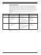
Networking Cards Technical Data | en 6 Technical Data 6.1 Common parameters of all three networking cards 6.1.1 Environmental 6.1.2 Environment: Indoor, dry Relative humidity: 5% to 93%, non-condensing Temperature (operating): 0°C to +49°C (+32°F to +120°F) 15 Mechanical Dimensions: 6.16 in. x 2.87 in. 1.20 in. (156.5 mm x 73 mm x 30.5 mm) Weight: 3.13 oz (88.
en | Technical Data F.01U.214.374 | 01 | 2012.08 Networking Cards Installation Manual Bosch Security System, Inc.
Bosch Security System, Inc. 130 Perinton Parkway Fairport, NY 14450 USA www.boschsecurity.us © Bosch Security System, Inc.