FPP-RNAC-8A-4C Operation and Installation Guide EN Remote NAC Power Supply
FPP-RNAC-8A-4C | Operation and Installation Guide | Notice to Users, Installers, Authorities Having Jurisdiction, and other involved parties: This product incorporates fieldprogrammable software. In order for the product to comply with the requirements in the Standard for Control Units and Accessories for Fire Alarm Systems, UL864, certain programming features or options must be limited to specific values or not used at all as indicated below.
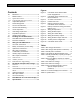
FPP-RNAC-8A-4C | Operation and Installation Guide | . Contents 1.0 1.1 1.1.1 1.1.2 1.2 1.3 1.4 1.5 1.6 1.7 1.8 1.9 2.0 2.1 2.2 3.0 3.1 3.2 3.3 3.4 3.5 3.6 3.7 3.7.1 3.7.2 3.7.3 4.0 4.1 4.2 4.3 4.4 4.5 4.6 5.0 6.0 Overview ...........................................................4 Module Control...................................................4 Option Bus Control ...........................................4 Conventional NAC Input Control ...................4 Output Bell Operation ......................
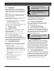
FPP-RNAC-8A-4C | Operation and Installation Guide | 1.0 All outputs are synchronized if the conventional inputs are activating the FPP-RNAC-8A-4C. 1.0 Overview The FPP-RNAC-8A-4C is a Remote Notification Appliance Circuit (NAC) Power Supply designed to add four additional NACs (NFPA 72 Class B, Style Y or Class A, Style Z) to a Fire Alarm Control Panel (FACP). The FPP-RNAC-8A-4C is supervised by the control panel. It consists of the controller board, backup batteries, and enclosure.
FPP-RNAC-8A-4C | Operation and Installation Guide | . 1.8 Expander Supervision Auxiliary Power Supply 1.9 A watchdog supervises the operation of the FPP-RNAC-8A-4C processor and attempts to restart it if it fails. If the processor does not restart, or the power fails entirely, the installer-supplied EOL device disconnects from the input to report the trouble condition. If power is available, the System Trouble LED lights if the system encounters an error.
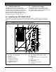
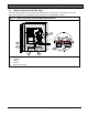
FPP-RNAC-8A-4C | Operation and Installation Guide | 2.0 2.1 Installing the FPP-RNAC-8A-4C FPP-RNAC-8A-4C Board Installation The FPP-RNAC-8A-4C board is staticsensitive. Touch ground before handling the board. Doing so discharges any static electricity in your body. 1. Connect the ground wire. 2. Insert the two support posts into the control retainer holes as shown in Figure 2 on page 7. 3. Slide the top of the board into the retainer tabs (the slots under the top of the frame).
FPP-RNAC-8A-4C | Operation and Installation Guide | 2.0 Installing the FPP-RNAC-8A-4C .
FPP-RNAC-8A-4C | Operation and Installation Guide | 3.0 Wiring the FPP-RNAC-8A-4C 3.0 Wiring the FPP-RNAC-8A-4C All terminals are fully protected against electrostatic discharge (ESD) and transients. Use wire gauge based on Table 1 and Table 2. The terminals can accommodate up to 12 AWG (2.0 mm) wire. Table 1: Wire Gauge Calculations Line No. 1 Description Calculation Guaranteed minimum NAC voltage at full load.
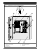
FPP-RNAC-8A-4C | Operation and Installation Guide | . Figure 3: AC Power Connections Figure 4: Install Ferrite Core 4 3 1 1 2 3 4 5 6 GN L 2 5 6 AC input select switch AC power terminal Ground Neutral Line (120 VAC or 240 VAC) Ferrite core 1 Ferrite core Install the Line and Neutral power connections through the ferrite core as shown in Figure 4. Bosch Security Systems, Inc.
FPP-RNAC-8A-4C | Operation and Installation Guide | 3.2 Battery Connections (24 VDC Only) The backup battery plugs into the terminals marked BATTERY+ and BATTERY- at the lower center of the board (refer to Figure 5). The FPP-RNAC-8A-4C requires two backup batteries in series.
FPP-RNAC-8A-4C | Operation and Installation Guide | .
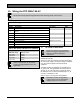
FPP-RNAC-8A-4C | Operation and Installation Guide | You can use the format in Table 3 to calculate the required battery size to support the system. Use Table 4 and Table 5 on page 13 to estimate the required battery size.
FPP-RNAC-8A-4C | Operation and Installation Guide | . Table 5: Standby Load Battery Capacity (in ampere-hours [Ah]) Total Standby Current Capacity Required for: 12 hr 100 to 300 mA 300 to 500 mA 500 to 700 mA 700 to 900 mA 900 mA to 1.1 A 1.1 to 1.3 A 1.3 to 1.5 A 1.5 to 1.7 A 1.7 to 1.9 A 1.9 to 2.1 A 2.1 to 2.3 A 2.3 to 2.5 A 2.5 to 2.7 A 24 hr 4.0 6.6 9.2 11.9 14.5 172 19.8 22.4 25.1 27.7 30.4 33.0 35.6 7.9 13.2 18.5 23.8 29.0 34.3 39.6 36 hr 11.9 19.8 27.7 35.6 48 hr 15.8 26.4 37.0 60 hr 19.
FPP-RNAC-8A-4C | Operation and Installation Guide | 3.3 The FPP-RNAC-8A-4C can be placed anywhere on an FACP’s NAC circuit. Option Bus Connections The option bus (if used) runs to the terminals labeled Y, G, B, and R (refer to Figure 7). You can use the option bus connection with a Bosch Security Systems, Inc. FPA-1000 or FPD-7024 Fire Alarm Control/Communicator.
FPP-RNAC-8A-4C | Operation and Installation Guide | . 3.5 Trouble Relay Connections 3.6 The trouble relay provides one set of Form C contacts for connection of an appliance of choice. The relay can be wired in series with the auxiliary output to provide power to the appliance. The relay deactivates by the controlling section of the board to indicate a fault condition. Refer to Figure 9 for wiring details.
FPP-RNAC-8A-4C | Operation and Installation Guide | 3.7.2 Figure 11: Wiring the NAC outputs and EOL Auxiliary Circuits The FPP-RNAC-8A-4C can be configured to supply constant auxiliary power through its NAC outputs. 1 Reverse polarity connections of some notification appliances might not be detected by the FPP-RNAC-8A-4C NAC supervision. Ensure that the notification appliances are connected properly and tested before installation is completed.
FPP-RNAC-8A-4C | Operation and Installation Guide | 4.0 DIP Switch and Option Bus Settings . 4.1 4.
FPP-RNAC-8A-4C | Operation and Installation Guide | 4.0 4.
FPP-RNAC-8A-4C | Operation and Installation Guide | 4.0 DIP Switch and Option Bus Settings . 4.3 Conventional (Polarity Reversal) Inputs 1 and 2 Two factors determine how the four NAC outputs respond to input: • Output protocol set on Switch S1 (refer to Table 7 on page 17) • Setting of Position 0 of Switch S2 (refer to Table 8 on page 18 Table 9 shows the output responses to the input on NAC inputs 1 and 2, based on the combined DIP switch settings. When an input is OFF, its polarity is reversed.
FPP-RNAC-8A-4C | Operation and Installation Guide | 4.0 4.4 DIP Switch and Option Bus Settings Option Bus Address To activate a new address, remove the AC and battery power from the FPP-RNAC-8A-4C. Wait 60 sec. Restore the power after it is removed. The new address becomes active after power is restored to the FPP-RNAC-8A-4C. The FPP-RNAC-8A-4C needs its own address (1 to 14) when using the option bus connection. Use Switch S2, Positions 3 through 6.
FPP-RNAC-8A-4C | Operation and Installation Guide | 5.0 FPP-RNAC-8A-4C Local Status Display . 5.0 FPP-RNAC-8A-4C Local Status Display LED indicators are provided for AC OK (green), inputs active (red), system fault (yellow), ground fault (yellow), and NAC 1-4 troubles (yellow). Refer to Figure 1 on page 5 for the location of each LED on the board. Refer to Table 10 for the label, color, and description of each on-board LED.
FPP-RNAC-8A-4C | Operation and Installation Guide | 5.0 FPP-RNAC-8A-4C Local Status Display Table 10: Local Status Display LED Functions (continued) LED 3 Label SYSTEM TROUBLE Color Yellow Description Blink Count (display priority) 1 2 3 4 5 6 7 Description (The Trouble Relay activates or changes state.) Any memory fault (RAM, FLASH, watchdog, unexpected interruptions, stack corruption). Power supply overvoltage. Low battery or missing battery Battery charger circuit trouble.
FPP-RNAC-8A-4C | Operation and Installation Guide | 6.0 Specifications . 6.0 Specifications Table 11: Specifications Enclosure (including a keyed lock and mounting hardware) Dimensions (HxWxD) 14.75 in. X 12.75 in. X 3.5 in. (37.5 cm x 32.
FPP-RNAC-8A-4C | Operation and Installation Guide | 6.0 Specifications Table 11: Specifications (continued) Trouble Relay Output Contact Type Contact Rating Form C 1.5 A, 30 VDC resistive load AC Trouble Relay Output Contact Type Form C Contact Rating 1.5 A, 30 VDC resistive load Power Output Circuit when Notification Appliance Circuit (NAC) is Configured as a Power Output Circuit Output Voltage 24 VDC Nominal Range for Compatibility 19.6 to 27.5 VDC Output Current 1.
FPP-RNAC-8A-4C | Operation and Installation Guide | 6.0 Specifications . Bosch Security Systems, Inc.
Bosch Security Systems, Inc. 130 Perinton Parkway Fairport, NY 14450-9199 (800) 289-0096 © 2009 Bosch Security Systems, Inc.