
Operation Manual


6 720 645 347 (2010/09)
14 | Installation (for contractors only)
3 Installation (for contractors only)
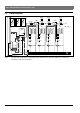
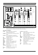
The detailed system scheme for installing the
hydraulic components and the associated control
devices can be found in the technical guides or
tender specifications.
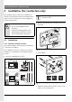
3.1 Installation
3.1.1 Fitting the heating controller
The control quality of the controller is dependent
on where it is installed.
The installation location (= lead room) must be
suitable for controlling the associated heating
circuits.
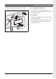
B Select the installation location.
Fig. 5
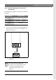
B Remove the top section and slide cover from
the base.
Fig. 6
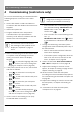
B Fit the base.
Fig. 7
B Make the electrical connections (Æ Fig. 11 on
page 17 or 9 on page 16).
DANGER: Risk of electric shock!
B Prior to the installation of this
accessory:
Isolate the heating appliance and
all other BUS subscribers from the
power supply (220 to 240 V AC).
6 720 612 481-03.1R
0,3 m0,3 m
1,2 - 1,5 m
0,6 m
119 mm
134 mm
35 mm
The mounting surface on the wall
should be level.
1.
2.
3.
6 720 612 220-27.1J
6 720 645 340-07.1O
6 mm 3,5 mm6 mm