
Use and Care Manual


16
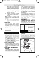
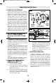
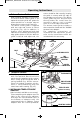
USING SELF-PILOTED BITS
S
elf-piloted bits have an integral
round tip or ball bearing which rides
against the work surface above or
below the cutter to control horizontal
cutting depth (Fig. 15). When using
these bits, neither the roller guide or
the straight guide is required. When
guiding against a laminated surface,
use wax or other lubricant and do not
apply excess pressure or the piloted
end may mar the work. Bearing pilots
must be kept clean and free of
adhesive or other residue. Router bit
bearings are sealed and permanently
lubricated, and should be replaced
when they no longer turn freely to
avoid damaging the work surface.
PR110 Round Subbase and
Use of Template Guide
Bushings with PR101 Fixed
base
(Available as optional accessories)
Optional large round subbases are
available separately and allow various
template guide bushings to be used
with the palm routers.
Template guide bushings are used to
guide the router to repeatedly make
consistent openings and inlays using
various templates (also referred to as
patterns and jigs). Templates for
standard routing applications are
available commercially and templates
for specialty applications are typically
made by users for their specific
needs.
The PR110 Round Subbase accepts
threaded template guide adapters.
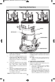
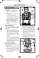
PR110 ATTACHMENT ROUND
SUBBASE OF THREADED
TEMPLATE GUIDE (Fig. 16)
1. Remove regular subbase.
2. Loosely attach round subbase
using panhead screws that come
with that accessory.
3. Attach the threaded template guide
by putting the template guide
through the bottom and attaching
the ring from the top.
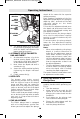
4. Center the template guide around
the bit. (The optional Bosch
RA1151 Centering device can be
used to ensure that the template
guide is properly centered.)
5. Tighten the panhead screws to
hold the template guide and
subbase in position.
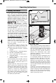
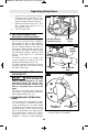
CREATING TEMPLATES
Template patterns can be made of
plywood, hardboard, metal or even
plastic. The design can be cut with a
router, jigsaw, or other suitable
cutting tool. Remember that the
pattern will have to be made to
compensate for the distance between
the router bit and the template guide
(the “offset”), as the final workpiece
will differ in size from the template
pattern by that amount, due to the bit
position (Fig. 17).
WORKPIECE
ROUTER BIT
OFFSET
TEMPLATE
GUIDE
TEMPLATE
PATTERN
ROUTER
SUBBASE
FIG. 16
FIG. 17
PR110 SUBBASE
TEMPLATE
GUIDE RING
ROUTER
BASE
PANHEAD
SCREWS
TEMPLATE
GUIDE
COLLET CHUCK
Operating Instructions
2610052572_GKF125CE 9/18/18 12:11 PM Page 16