
Operation Manual

English | 25
Bosch Power Tools 1 609 929 R32 | (6.3.08)
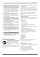
f Use appropriate detectors to determine if
utility lines are hidden in the work area or
call the local utility company for assistance.
Contact with electric lines can lead to fire
and electric shock. Damaging a gas line can
lead to explosion. Penetrating a water line
causes property damage or may cause an
electric shock.
f Do not use blunt or damaged router bits.
Blunt or damaged router bits cause in-
creased friction, can become jammed and
lead to imbalance.
f When working with the machine, always
hold it firmly with both hands and provide
for a secure stance. The power tool is guided
more secure with both hands.
f Secure the workpiece. A workpiece clamped
with clamping devices or in a vice is held
more secure than by hand.
f Keep your workplace clean. Blends of mate-
rials are particularly dangerous. Dust from
light alloys can burn or explode.
f Always wait until the machine has come to
a complete stop before placing it down. The
tool insert can jam and lead to loss of control
over the power tool.
f Never use the machine with a damaged ca-
ble. Do not touch the damaged cable and
pull the mains plug when the cable is dam-
aged while working. Damaged cables in-
crease the risk of an electric shock.
Functional Description
Read all safety warnings and all in-
structions. Failure to follow the
warnings and instructions may re-
sult in electric shock, fire and/or se-
rious injury.
While reading the operating instructions, unfold
the graphics page for the machine and leave it
open.
Intended Use
The machine is intended for routing grooves,
edges, profiles and elongated holes as well as
for copy routing in wood, plastic and light build-
ing materials, while resting firmly on the work-
piece.
With reduced speed and with appropriate rout-
ing bits, non-ferrous alloys can also be ma-
chined.
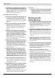
Product Features
The numbering of the product features refers to
the illustration of the machine on the graphics
page.
1 Routing motor
2 Plunge base
3 Non-plunge base
4 Thumbwheel for speed preselection
5 On/Off switch
6 Scale for depth-of-cut adjustment (plunge
base)
7 Depth stop (plunge base)
8 Slide with index mark (plunge base)
9 Wing bolt for depth stop (plunge base)
10 Sleeve for depth-of-cut fine adjustment
(plunge base)
11 Dust boot
12 Base plate
13 Step buffer
14 Guide plate
15 Handle
16 Mark on plunge base/non-plunge base
17 Tightening nut with collet
18 Router bit*
19 Chip shield (plunge base)
20 Clamping lever for plunge base/non-plunge
base
21 Release lever for plunge base
22 Seat for parallel guide rods
23 Chip shield (non-plunge base)
24 Scale for depth-of-cut adjustment
(non-plunge base)
OBJ_BUCH-100-003.book Page 25 Thursday, March 6, 2008 10:50 AM