
Product Manual


-19-
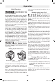
X and Y Axes Calibration
– Make sure the laser level is turned off.
– Mount the laser level in the horizontal position
on a tripod or a firm and level surface in front of
a wall.
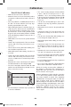
– Place it at a distance of 100 ft (30 m) in front of
the wall. The X-axis indicator on the top cage
must be perpendicular to the wall.
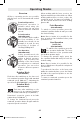
– While holding the button for dual-axis slope op-
eration 2, press and release the On/Off button
1. Release the button for dual-axis slope opera-
tion 2 when the X axis leveling indicator LED
5 (green) and shock-warning indicator LED 11
(red) start flashing simultaneously at a rate of
1x per second.
– Wait until the tool is leveled - the prism will start
rotating.
– Transfer the height (point I) of the laser beam
onto the wall. If necessary, use the laser receiv-
er to do so.
– Turn the laser level by 180° while making sure
not to shift the height of the tool.
– Wait until the prism starts rotating - then the tool
is leveled.
– Transfer the height (point II) of the laser beam
onto the wall. If necessary, use the laser receiv-
er to do so. Make sure it is a vertical as possible
to point I.
– Determine the exact center between the points
I and II and mark it on the wall (point III).
– Press the lower/upper direction button 4 or 12
until the laser beam matches point III. Use the
laser receiver if necessary.
– Press the button for dual-axis slope operation 2
to save the calibration.
– The X axis leveling indicator LED 5 will flash
6 times, and the tool will proceed to Y axis
calibration - the Y axis leveling indicator LED
5 (green) and shock-warning indicator LED 11
(red) start flashing simultaneously at a rate of
1x per sec.
– Turn the laser level by 90 degrees (The Y-axis
indicator on the top cage must be perpendicu-
lar to the wall).
– Wait until the tool is leveled - the prism will start
rotating.
– Transfer the height “Y1” of the laser beam onto
the wall. If necessary, use the laser receiver to
do so.
– Turn the laser level by 180° while making sure
not to change the height of the tool.
– Wait until the prism starts rotating - then the tool
is leveled.
– Transfer the height “Y2” of the laser beam onto
the wall. If necessary, use the laser receiver to
do so. Make sure it is as vertical as possible to
“Y1”.
– Determine the exact center between the points
“Y1” and “Y2” and mark it on the wall (“Y3”).
– Press the lower/upper direction buttons 4 or 12
until the laser beam matches “Y3”. Use the la-
ser receiver if necessary.
– Press the button for dual-axis slope operation 2
to save the calibration.
– The Y axis leveling indicator LED 5 will flash 6
times and tool will exit the calibration mode.
Check the leveling accuracy after calibration. If
the deviation is still outside of the maximum per-
mitted limit, have the laser level checked by a
Bosch customer service agent.
If during adjustment of either axis the respective
X or Y axis leveling indicator LED 5 starts flash-
ing red the deviation is outside of the maximum
permitted limit. Pressing the button for dual-axis
slope operation 2 will exit the calibration mode
without saving the new value and an error will be
shown by simultaneously flashing the X and Y lev-
eling indicator LEDs 5 at a rate of 3x per second.
Restart the calibration and if the error persists,
have the laser tool checked by a Bosch customer
service agent.
Calibration
2610055315 GRL2000-40 02-20.indd 19 3/2/20 7:07 AM