
Use and Care Manual


Abrasive Type 27 Grinding Wheel &
Sanding Flap Disk Assembly
Your tool is equipped with a threaded spindle
for mounting non-threaded hub accessories.
Always use the supplied backing flange with
a lock nut. Always ensure that arbor diameter
matches accessory diameter.
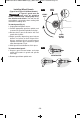
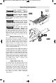
To install grinding wheel or flap disk
(Fig. 7):
1. Unplug tool from power source.
2. Install and adjust type 27 grinding guard to
the proper position for grinding as shown in
figure 5.
3. Place the backing flange on the spindle.
Turn flange until it locks with the base of the
spindle.
4. Place the grinding wheel onto the spindle
and align the arbor hole of the grinding
wheel with the shoulder of the backing
flange.
5. Thread the lock nut onto the spindle with the
lock nut relief facing the accessory.
6. Tighten lock nut with supplied lock nut
wrench while holding spindle lock.
TO REMOVE: Reverse procedure.
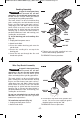
When using spin-on wheels:
Follow steps 1 & 2, then thread wheel
directly onto spindle without using the
supplied flanges.
TO REMOVE: Reverse procedure.
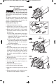
All parts of a spin-on wheel must be within lip
of grinding guard (Fig. 8). If spin-on wheel is
past lip of guard, do not use that wheel as it
does not fit on this grinder.
Do not use accessories
that run eccentrically. The
tool will vibrate excessively and may cause
loss of control and the accessory may burst.
!
WARNING
LOCK NUT
TYPE 27
GRINDING
WHEEL
BACKING
FLANGE
SPINDLE
-14-
SPINDLE
TYPE 27
WHEEL GUARD
FIG. 7
BACKING
FLANGE
TYPE 27 SPIN-ON
GRINDING WHEEL
TYPE 27
GRINDING
WHEEL
LOCK NUT
FIG. 8
SPIN-ON
WHEEL
LIP OF
GUARD
2610041357 09-15 GWS10 GWS13.qxp_GWS series 9/18/15 12:56 PM Page 14